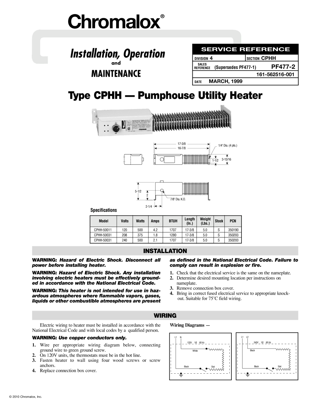
PF477-2 specifications
Chromalox PF477-2 is a state-of-the-art electric heater designed for a variety of industrial applications. Renowned for its efficiency and versatility, the PF477-2 incorporates advanced heating technologies, making it an ideal choice for processes requiring precise temperature control. Featuring a robust construction, the heater is built to withstand harsh environments, ensuring longevity and reliability.One of the main features of the Chromalox PF477-2 is its high-performance heating element. The unit utilizes high-density, ceramic-insulated, and nickel-chromium metal heating wires that provide rapid heat-up times and uniform heat distribution. This capability not only improves the operational efficiency but also enhances energy savings, making it an eco-friendly option for companies aiming to reduce their carbon footprint.
The PF477-2 heater comes with a variety of control options, allowing for easy integration into existing systems. With its advanced digital temperature controller, users can achieve precise settings, monitor real-time temperature data, and manage heating cycles effectively. This level of control enables facilities to optimize their processes, improving product quality and minimizing waste.
Durability is another critical aspect of the Chromalox PF477-2. It is designed with a heavy-duty stainless-steel housing, providing excellent corrosion and wear resistance. This feature ensures that the heater can operate effectively in adverse conditions, such as high humidity or exposure to chemicals, without compromising performance.
Safety is paramount in any industrial setting, and the PF477-2 is equipped with multiple safety features. It includes over-temperature protection, which automatically shuts down the heater in case of an operational anomaly. Additionally, the unit has built-in thermal sensors that monitor the heating elements, ensuring they never exceed safe operating limits.
In summary, the Chromalox PF477-2 electric heater stands out due to its advanced heating technologies, durable construction, and exceptional control features. These characteristics make it suitable for a wide range of applications, including chemical processing, food and beverage, and pharmaceutical manufacturing. Companies looking for a reliable, efficient, and safe heating solution can greatly benefit from integrating the Chromalox PF477-2 into their operations. With its commitment to high performance and sustainability, it represents a valuable asset for any industrial heating requirement.