MAINTENANCE
ELECTRIC SHOCK HAZARD. Disconnect heater from power supply before servicing and/or inspecting the heater; failure to do so may result in electrical shock.
Replace or repair damaged cords or plugs immediately. Check tight- ness of all electrical connections prior to energizing Dragon. Blow out or vacuum away any dirt or debris that may have accumulated around the control enclosure fan motor or heating elements.
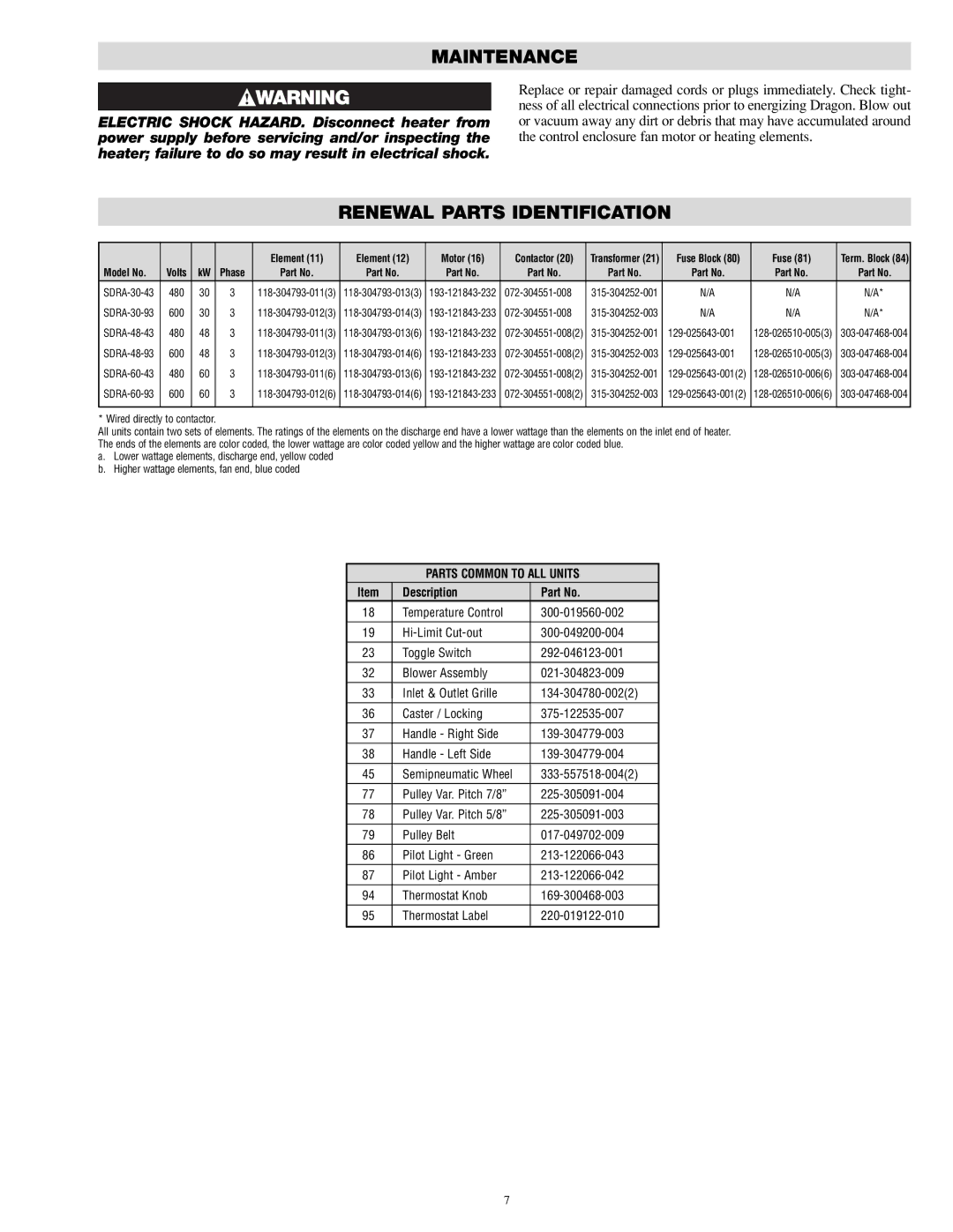
RENEWAL PARTS IDENTIFICATION
|
|
|
| Element (11) | Element (12) | Motor (16) | Contactor (20) | Transformer (21) | Fuse Block (80) | Fuse (81) | Term. Block (84) |
Model No. | Volts | kW | Phase | Part No. | Part No. | Part No. | Part No. | Part No. | Part No. | Part No. | Part No. |
480 | 30 | 3 | N/A | N/A | N/A* | ||||||
600 | 30 | 3 | N/A | N/A | N/A* | ||||||
480 | 48 | 3 |
| ||||||||
600 | 48 | 3 | |||||||||
480 | 60 | 3 | |||||||||
600 | 60 | 3 | |||||||||
|
|
|
|
|
|
|
|
|
|
|
|
* Wired directly to contactor.
All units contain two sets of elements. The ratings of the elements on the discharge end have a lower wattage than the elements on the inlet end of heater. The ends of the elements are color coded, the lower wattage are color coded yellow and the higher wattage are color coded blue.
a.Lower wattage elements, discharge end, yellow coded
b.Higher wattage elements, fan end, blue coded
PARTS COMMON TO ALL UNITS
Item | Description | Part No. | |
18 | Temperature Control |
| |
|
|
|
|
19 |
| ||
23 | Toggle Switch |
| |
32 | Blower Assembly |
| |
|
|
|
|
33 | Inlet & Outlet Grille |
| |
36 | Caster / Locking |
| |
37 | Handle - Right Side |
| |
|
|
|
|
38 | Handle - Left Side |
| |
45 | Semipneumatic Wheel |
| |
77 | Pulley Var. Pitch 7/8” |
| |
|
|
|
|
78 | Pulley Var. Pitch 5/8” |
| |
79 | Pulley Belt |
| |
86 | Pilot Light - Green |
| |
|
|
|
|
87 | Pilot Light - Amber |
| |
94 | Thermostat Knob |
| |
95 | Thermostat Label |
| |
|
|
|
|
7
