Feature | Description/Part Numbers | |
|
| |
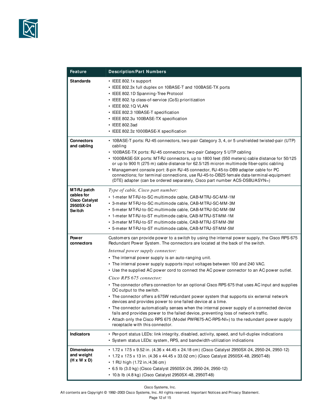
Standards | • IEEE 802.1x support | |
| • IEEE 802.3x full duplex on | |
| • IEEE 802.1D | |
| • IEEE 802.1p | |
| • IEEE 802.1Q VLAN | |
| • IEEE 802.3 | |
| • IEEE 802.3u | |
| • IEEE 802.3ad | |
| • IEEE 802.3z | |
|
| |
Connectors | • | |
and cabling | cabling | |
| • | |
| • | |
| or up to 900 ft (275 m) cable distance for 62.5/125 micron multimode | |
| • Management console port: | |
| connections; for terminal connections, use | |
| (DTE) adapter (can be ordered separately, Cisco part number | |
|
| |
| Type of cable, Cisco part number: | |
cables for | • | |
Cisco Catalyst | ||
• | ||
| ||
• | ||
Switch | ||
| • | |
| • | |
| • | |
|
| |
Power | Customers can provide power to a switch by using the internal power supply, the Cisco RPS 675 | |
connectors | Redundant Power System. The connectors are located at the back of the switch. | |
| Internal power supply connector: | |
| • The internal power supply is an | |
| • The internal power supply supports input voltages between 100 and 240 VAC. | |
| • Use the supplied AC power cord to connect the AC power connector to an AC power outlet. | |
| Cisco RPS 675 connector: | |
| • The connector offers connection for an optional Cisco RPS 675 that uses AC input and supplies | |
| DC output to the switch. | |
| • The connector offers a 675W redundant power system that supports six external network | |
| devices and provides power to one failed device at a time. | |
| • The connector automatically senses when the internal power supply of a connected device | |
| fails and provides power to the failed device, preventing loss of network traffic. | |
| • Attach only the Cisco RPS 675 (Model | |
| receptacle with this connector. | |
|
| |
Indicators | • | |
| • System status LEDs: system, RPS, and | |
|
| |
Dimensions | • 1.72 x 17.5 x 9.52 in. (4.36 x 44.45 x 24.18 cm) (Cisco Catalyst | |
and weight | • 1.72 x 17.5 x 13 in. (4.36 x 44.45 x 33.02 cm) (Cisco Catalyst | |
(H x W x D) | • 1 RU high (1.72 in./4.36 cm) | |
| ||
| • 6.5 lb (3.0 kg) (Cisco Catalyst | |
| • 10.b lb (4.8 kg) (Cisco Catalyst | |
|
|
Cisco Systems, Inc.
All contents are Copyright ©
Page 12 of 15
