3750 specifications
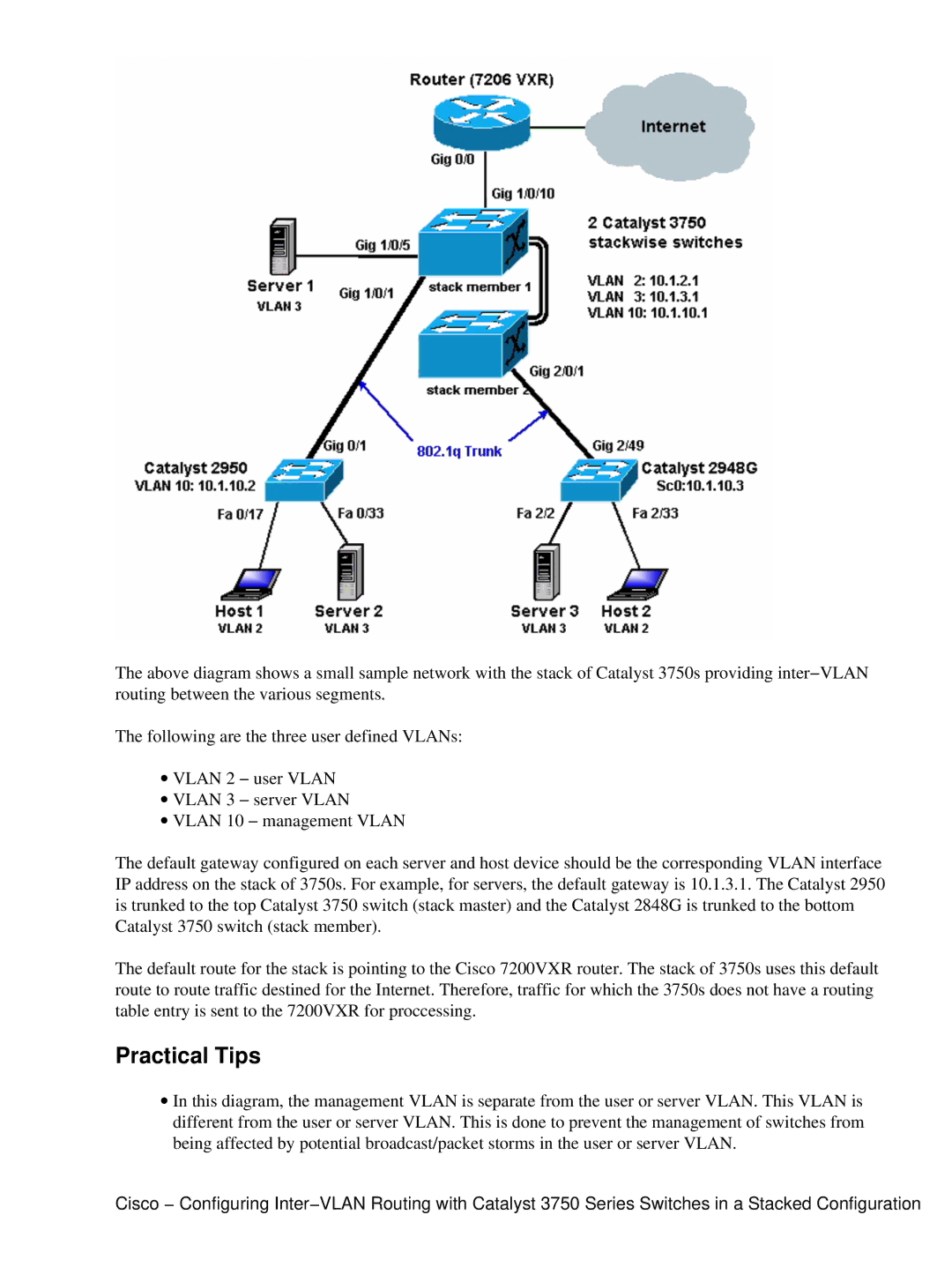
The Cisco Systems 3750 series is a family of enterprise-class stackable switches that were designed to provide high-performance networking solutions for organizations requiring robust management features, security, and scalability. Known for their reliability and advanced capabilities, the 3750 series is particularly aimed at accommodating the demands of LAN environments in organizations ranging from small businesses to large enterprises.One of the defining features of the Cisco 3750 series is its StackWise technology. This innovative feature enables the stacking of up to nine switches together, allowing them to function as a single logical unit. This results in simplified management, higher redundancy, and increased scalability. The StackWise technology allows for seamless failover and enhanced bandwidth between the stacked switches.
In terms of performance, the 3750 series supports Layer 2 and Layer 3 switching, offering routing capabilities to handle both traditional and modern network demands. It is equipped with advanced Quality of Service (QoS) features, ensuring that critical applications such as voice and video are prioritized for optimal performance.
The Cisco 3750 also features extensive security capabilities. It incorporates features such as IEEE 802.1X authentication, DHCP snooping, and dynamic ARP inspection to protect against unauthorized access and various network attacks. These enhancements help maintain data integrity and secure communications across the network.
Another noteworthy characteristic of the 3750 series is its support for Power over Ethernet (PoE). PoE allows for the delivery of power over Ethernet cables to connected devices, such as IP phones and wireless access points, facilitating simpler installations and reducing the need for additional power outlets.
The Cisco 3750 series also provides a comprehensive set of management tools. With features like Cisco's Embedded Event Manager (EEM) and extensive SNMP support, network administrators can efficiently monitor and manage network performance, troubleshoot issues, and maintain high availability.
Additionally, the series is compatible with Cisco's IOS software, which provides a rich set of features, including advanced routing protocols, multicast support, and extensive security options, further enhancing the functionality and versatility of the switches.
Overall, the Cisco Systems 3750 series stands out for its stackable design, high-performance features, security capabilities, and management tools, making it a popular choice for organizations looking for dependable and scalable networking solutions.

