Chapter 3 Configuring and Managing the IP Camera

Network Setup Windows

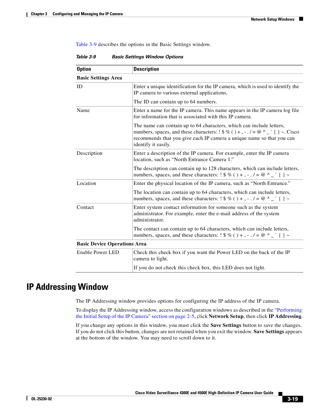
Table 3-9describes the options in the Basic Settings window.

Table 3-9 Basic Settings Window Options

Option

Description


Basic Settings Area


ID

Enter a unique identification for the IP camera, which is used to identify the


IP camera to various external applications.


The ID can contain up to 64 numbers.


Name

Enter a name for the IP camera. This name appears in the IP camera log file


for information that is associated with this IP camera.


The name can contain up to 64 characters, which can include letters,


numbers, spaces, and these characters: ! $ % ( ) + , - . / = @ ^ _ ` { } ~. Cisco


recommends that you give each IP camera a unique name so that you can


identify it easily.


Description

Enter a description of the IP camera. For example, enter the IP camera


location, such as “North Entrance Camera 1.”


The description can contain up to 128 characters, which can include letters,


numbers, spaces, and these characters: ! $ % ( ) + , - . / = @ ^ _ ` { } ~


Location

Enter the physical location of the IP camera, such as “North Entrance.”


The location can contain up to 64 characters, which can include letters,


numbers, spaces, and these characters: ! $ % ( ) + , - . / = @ ^ _ ` { } ~


Contact

Enter system contact information for someone such as the system


administrator. For example, enter the e-mail address of the system


administrator.


The contact can contain up to 64 characters, which can include letters,


numbers, spaces, and these characters: ! $ % ( ) + , - . / = @ ^ _ ` { } ~


Basic Device Operations Area

Enable Power LED

Check this check box if you want the Power LED on the back of the IP camera to light.

If you do not check this check box, this LED does not light.

IP Addressing Window

The IP Addressing window provides options for configuring the IP address of the IP camera.

To display the IP Addressing window, access the configuration windows as described in the “Performing the Initial Setup of the IP Camera” section on page 2-5, click Network Setup, then click IP Addressing.

If you change any options in this window, you must click the Save Settings button to save the changes. If you do not click this button, changes are not retained when you exit the window. Save Settings appears at the bottom of the window. You may need to scroll down to it.


Cisco Video Surveillance 4300E and 4500E High-Definition IP Camera User Guide


OL-25230-02


3-19


Page 45
Image 45
Cisco Systems 4300E manual IP Addressing Window, Basic Settings Area, Basic Device Operations Area

4300E specifications

The Cisco Systems 4300E Series is an advanced integrated service router designed to deliver high-performance, scalable, and secure networking solutions for enterprises. This versatile platform caters to a wide range of applications while ensuring reliability and flexibility in dynamic environments.

One of the standout features of the Cisco 4300E is its modular architecture, which allows organizations to tailor the router to their specific needs by adding or changing modules. This modularity is crucial for enterprises that require agility to adapt to evolving network demands. The router supports various network interface modules (NIMs), service modules (SMs), and high-speed WAN interface cards (HWICs), enabling seamless integration of various interfaces and features.

The Cisco 4300E is designed with performance in mind, capable of delivering high throughput and low latency, which is essential for applications such as voice, video, and data traffic. It supports robust performance with the capability of handling up to 2 Gbps of throughput, making it suitable for mid-sized to large enterprise branch offices.

Another key technology associated with the 4300E is Cisco’s Unified Communications and Collaboration suite. This integration facilitates voice, video, and messaging services across the network, ensuring efficient communication within organizations. Security features include advanced threat protection through Cisco’s integrated security services, such as firewall capabilities, VPN support, and intrusion prevention, ensuring that sensitive data remains secure.

The Cisco 4300E also supports Cisco’s DNA (Digital Network Architecture) capabilities, allowing for automation, analytics, and enhanced network visibility. This integration empowers network administrators to manage their infrastructure proactively, ensuring optimal performance and quick resolution of issues.

Additionally, the router is equipped with enhanced Quality of Service (QoS) capabilities, enabling prioritization of critical applications and traffic types. This feature is vital for maintaining high performance across diverse application requirements.

In conclusion, the Cisco 4300E Series routers stand out for their modular architecture, high performance, integrated security, and support for advanced networking technologies. These characteristics make them ideal for enterprises seeking a robust, flexible, and secure solution to meet their networking needs in an ever-evolving digital landscape. With the ability to seamlessly integrate various services and applications, the 4300E is a reliable choice for any organization looking to future-proof its network infrastructure.