3 Cisco 6130 |
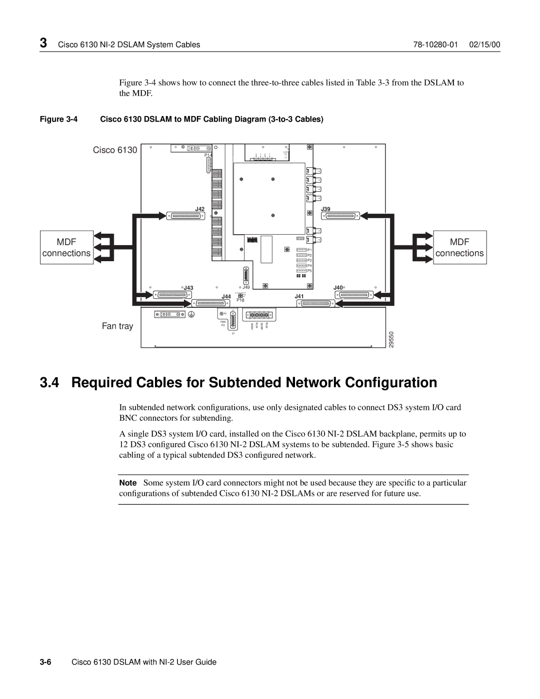
Figure 3-4 shows how to connect the three-to-three cables listed in Table 3-3 from the DSLAM to the MDF.
Figure 3-4 Cisco 6130 DSLAM to MDF Cabling Diagram (3-to-3 Cables)
Cisco 6130 |
|
|
|
|
|
| POOL |
|
| P14 |
| 48RTN- | 48V- B | 48RTN- | 48V- A | MODEM |
|
|
| OUT |
| |||||
|
|
|
|
|
|
| A |
|
| CRIT |
|
|
|
|
|
|
|
| MAJ |
|
|
|
|
|
|
|
| MIN |
|
|
|
|
|
|
|
| FAN |
|
|
|
|
|
|
|
| E2A |
|
|
|
|
|
|
|
| J42 |
|
|
|
|
|
| J39 |
MDF |
|
|
|
|
|
|
| MDF |
connections |
|
|
|
|
|
| P1 | connections |
|
|
|
|
|
| P2 | ||
|
|
|
|
|
|
| P3 |
|
|
|
|
|
|
|
| P4 |
|
|
|
|
|
|
|
| P5 |
|
| J43 | J49 |
|
|
|
|
| J40 |
| J44 | ANALOG TEST I/F |
|
|
|
| J41 |
|
| RING |
|
|
|
|
| ||
|
| TIP |
|
|
|
|
|
|
|
| P18 |
|
|
|
|
|
|
|
| J1 |
|
|
|
|
|
|
| P2 |
|
|
|
|
|
|
|
Fan tray | FAN | 48VA- | RTN | 48VB- |
| RTN |
|
|
P2 |
|
| 29550 | |||||
|
| J1 |
|
|
|
|
|
3.4 Required Cables for Subtended Network Configuration
In subtended network configurations, use only designated cables to connect DS3 system I/O card
BNC connectors for subtending.
A single DS3 system I/O card, installed on the Cisco 6130
Note Some system I/O card connectors might not be used because they are specific to a particular configurations of subtended Cisco 6130