Module Interfaces
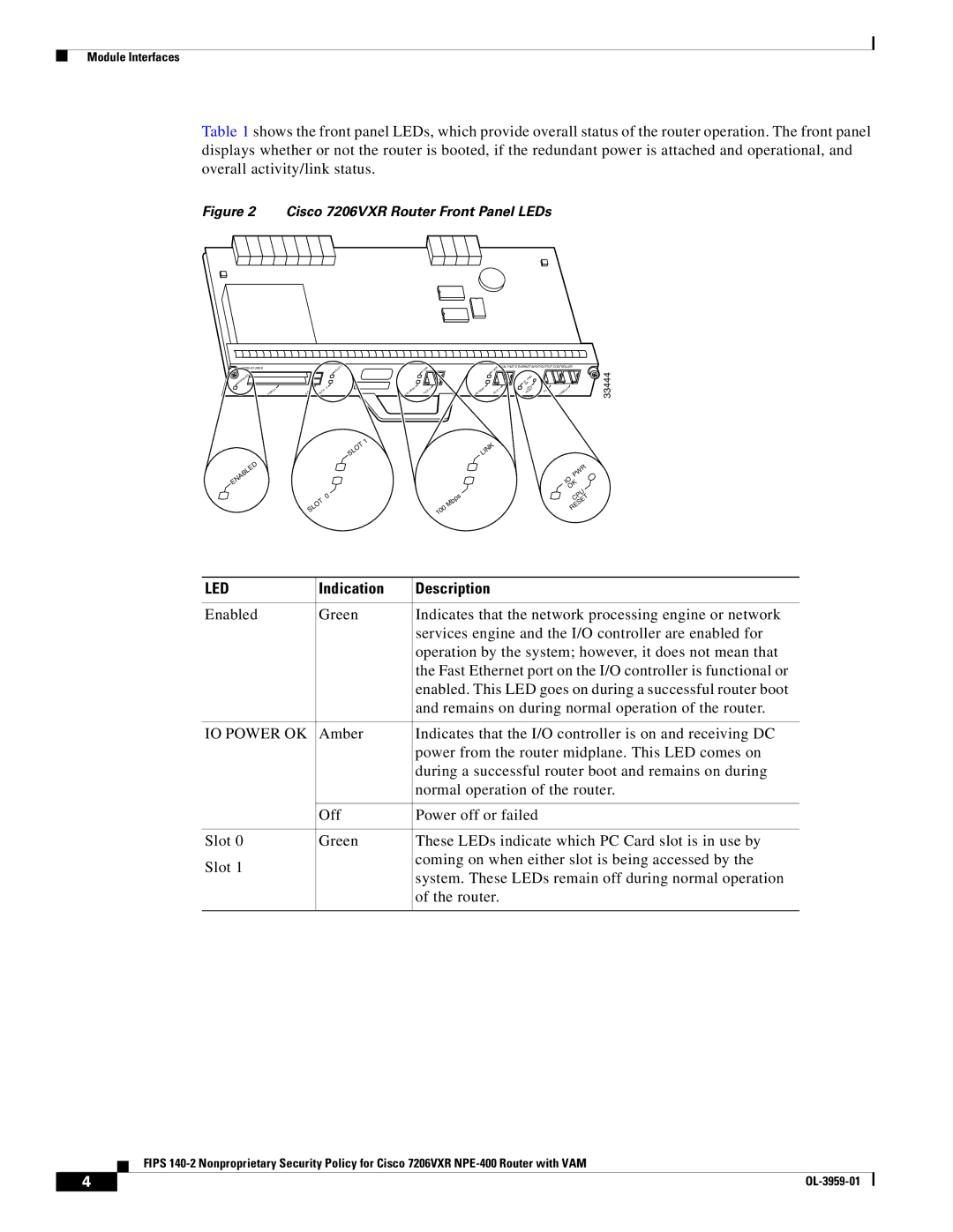
Table 1 shows the front panel LEDs, which provide overall status of the router operation. The front panel displays whether or not the router is booted, if the redundant power is attached and operational, and overall activity/link status.
Figure 2 Cisco 7206VXR Router Front Panel LEDs
ENABLED
PCMCIA
ENABLED
| SLOT | 1 |
| LINK |
|
|
| LINK | DUAL FAST ETHERNET INPUT/OUTPUT CONTROLLER |
| |||
|
|
|
|
|
|
|
|
|
| 33444 | |||
|
|
|
|
|
|
|
|
|
| R |
|
| |
|
|
|
|
|
|
|
|
|
| PW |
|
|
|
|
|
|
|
|
|
|
|
|
| IO |
|
|
|
|
|
|
|
|
|
|
|
|
| OK |
|
|
|
| 0 |
| 100 Mbps |
| 0 |
| 100 Mbps |
| 1 | CPU |
| CONSOLE |
|
EJECT | SLOT |
| FE/E |
|
| FE/E |
| RESET | AUX |
| |||
|
| SLOT | 1 |
|
|
|
|
|
|
|
|
|
|
|
|
|
|
|
| LINK |
|
|
|
|
| ||
|
|
|
|
|
|
|
|
|
|
|
| PWR |
|
|
|
|
|
|
|
|
|
|
|
|
| IO |
|
|
|
|
|
|
|
|
|
|
|
|
| OK |
|
| 0 |
|
|
|
|
| Mbps |
|
|
|
| CPU |
|
SLOT |
|
|
|
| 100 |
|
|
|
| RESET |
| ||
|
|
|
|
|
|
|
|
|
| ||||
|
|
|
|
|
|
|
|
|
|
|
|
| |
LED | Indication | Description |
|
|
|
Enabled | Green | Indicates that the network processing engine or network |
|
| services engine and the I/O controller are enabled for |
|
| operation by the system; however, it does not mean that |
|
| the Fast Ethernet port on the I/O controller is functional or |
|
| enabled. This LED goes on during a successful router boot |
|
| and remains on during normal operation of the router. |
|
|
|
IO POWER OK | Amber | Indicates that the I/O controller is on and receiving DC |
|
| power from the router midplane. This LED comes on |
|
| during a successful router boot and remains on during |
|
| normal operation of the router. |
|
|
|
| Off | Power off or failed |
|
|
|
Slot 0 | Green | These LEDs indicate which PC Card slot is in use by |
Slot 1 |
| coming on when either slot is being accessed by the |
| system. These LEDs remain off during normal operation | |
|
| |
|
| of the router. |
|
|
|
FIPS
4 |
| |
|
