AIRRM3000ACAK9 specifications
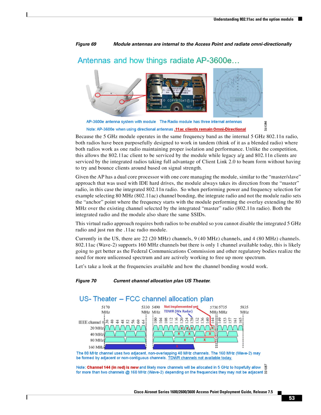
Cisco Systems has long been a leader in networking solutions, and one of its standout offerings in the wireless access point market is the AIR-RM3000-AK9 model. This device is designed to provide high-performance and reliable wireless connectivity for a wide range of applications, making it an ideal choice for organizations that demand robust networking capabilities.One of the main features of the AIR-RM3000-AK9 is its dual-band operation, which allows it to operate on both the 2.4 GHz and 5 GHz frequency bands. This dual-band capability enables the access point to support a greater number of devices and deliver higher data throughput, thereby enhancing the overall user experience. The access point can automatically select the best band, ensuring optimal performance based on network conditions and user requirements.
The device also supports the latest Wi-Fi 5 (802.11ac) standard, delivering impressive wireless speeds and improved capacity compared to previous generations. With Multi-User Multiple Input Multiple Output (MU-MIMO) technology, the AIR-RM3000-AK9 can communicate with multiple devices simultaneously. This feature is particularly advantageous in crowded environments, as it helps to reduce latency and increase overall network efficiency.
Security is another critical aspect of the AIR-RM3000-AK9. It offers advanced security protocols such as WPA2 and WPA3, ensuring that data remains protected as it traverses the wireless medium. Additionally, with Cisco's identity and access services, organizations can manage user access and maintain compliance with security policies.
The access point is also designed for easy deployment and management. With support for Cisco DNA Center, network administrators can leverage a centralized platform for monitoring, troubleshooting, and optimizing network performance. This capability is essential for reducing operational costs and improving overall network reliability.
Moreover, the AIR-RM3000-AK9 features advanced Quality of Service (QoS) capabilities to prioritize traffic, ensuring that critical applications receive the bandwidth they need for seamless operation. This feature is particularly beneficial for organizations that rely on real-time applications such as video conferencing and VoIP.
In summary, Cisco Systems AIR-RM3000-AK9 access point stands out due to its dual-band operation, support for Wi-Fi 5, MU-MIMO technology, robust security features, and ease of management. These characteristics make it an excellent choice for businesses seeking to enhance their wireless networking capabilities while ensuring high performance and security.

