CISCO805 specifications
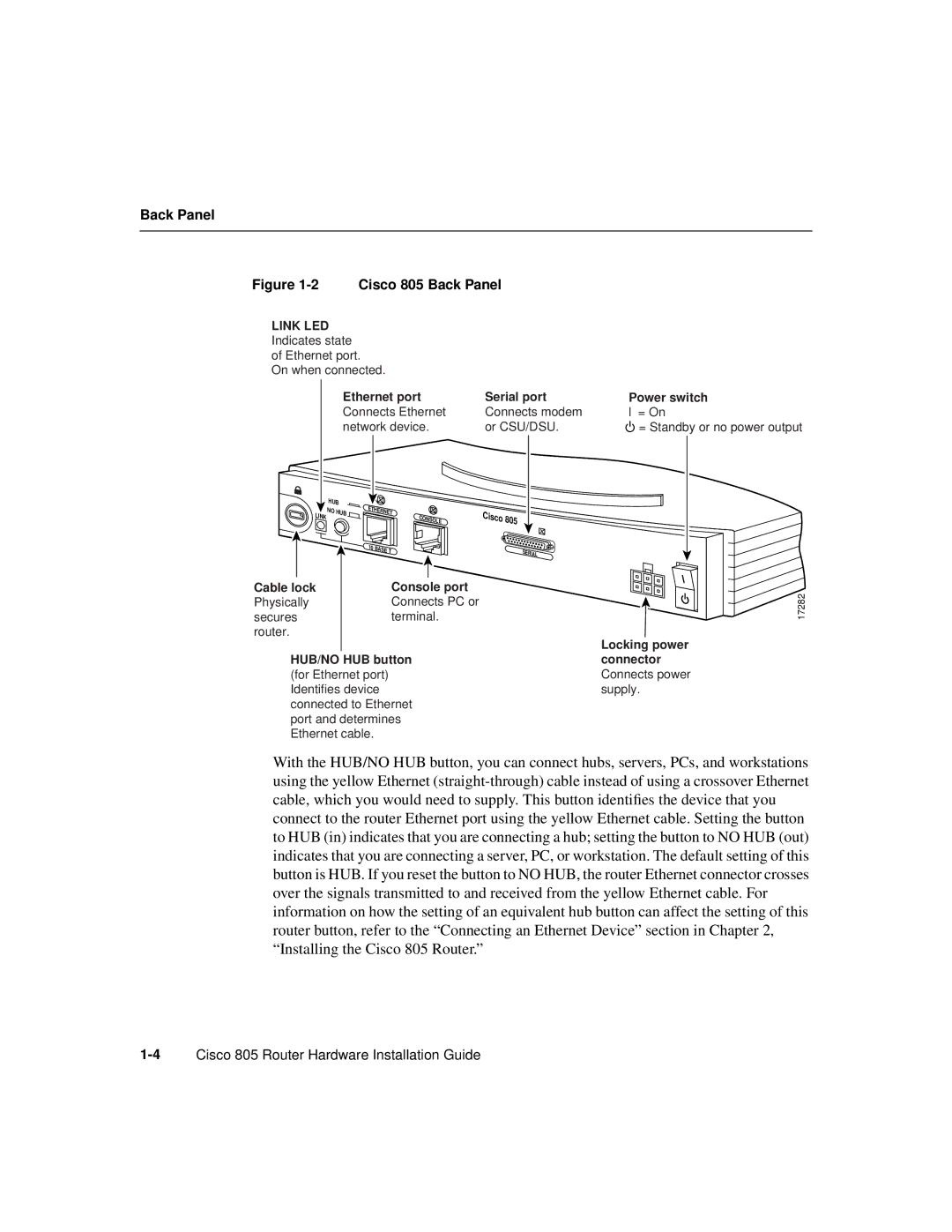
Cisco Systems has long been a leader in networking and cybersecurity solutions, and among its extensive range of products, the Cisco CISCO805 stands out as an essential device for small to medium-sized enterprises. The CISCO805 router is designed to meet the needs of organizations looking for reliable connectivity and robust security features without the complexity associated with larger enterprise solutions.One of the key features of the CISCO805 is its simple and efficient hardware design, which includes built-in support for both IPv4 and IPv6 protocols. This dual-stack capability allows businesses to transition smoothly into the future of networking while maintaining compatibility with existing infrastructure. The router offers multiple WAN interfaces, providing businesses with the flexibility to implement various internet connection types, including DSL, cable, or fiber.
In terms of performance, the CISCO805 is equipped with advanced processing capabilities that ensure high throughput and low latency. This makes it suitable for handling applications that demand significant bandwidth, including video conferencing, VoIP, and cloud-based services. Its modular architecture allows for easy upgrades, enabling organizations to scale their network with growing business needs.
Security is also a critical aspect of the CISCO805. The router incorporates multiple layers of security features, including built-in firewalls, intrusion detection systems, and VPN support, ensuring that sensitive data is protected against unauthorized access. Moreover, Cisco's Security Intelligence technology helps to provide real-time threat mitigation, making it an ideal solution for businesses concerned about cybersecurity risks.
Another noteworthy characteristic of the CISCO805 is its support for advanced networking technologies such as Quality of Service (QoS). This allows organizations to prioritize certain types of traffic, ensuring that mission-critical applications receive ample bandwidth, regardless of the total load on the network. Additionally, the router provides easy management features through Cisco’s intuitive web interface, allowing IT administrators to configure, monitor, and troubleshoot networks with ease.
With its combination of reliability, performance, and security features, the Cisco CISCO805 is a versatile solution that empowers businesses to build robust and efficient networks. It’s an ideal choice for organizations looking to enhance their connectivity while leveraging Cisco's trusted technology ecosystem.

