Chapter 1 Product Overview
Physical and Functional Description of Router
In the
•Modules A1 and B1 provide redundant power for system load zone 1 (the upper blower module and the upper card cage).
•Modules A2 and B2 provide redundant power for system load zone 2 (the switch fabric card cage, the lower card cage, and the lower blower module).
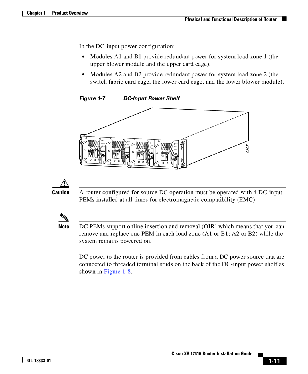
Figure 1-7 DC-Input Power Shelf
PWR OK |
|
| PWR OK |
FAULT | PWR OK |
PWR OK | |
| FAULT |
TEMP | FAULT |
FAULT | |
| TEMP |
| TEMP |
| TEMP |
26201
Caution A router configured for source DC operation must be operated with 4
Note DC PEMs support online insertion and removal (OIR) which means that you can remove and replace one PEM in each load zone (A1 or B1; A2 or B2) while the system remains powered on.
DC power to the router is provided from cables from a DC power source that are connected to threaded terminal studs on the back of the
|
| Cisco XR 12416 Router Installation Guide |
|
|
|
|
| ||
|
|
| ||
|
|
|