Data Sheet
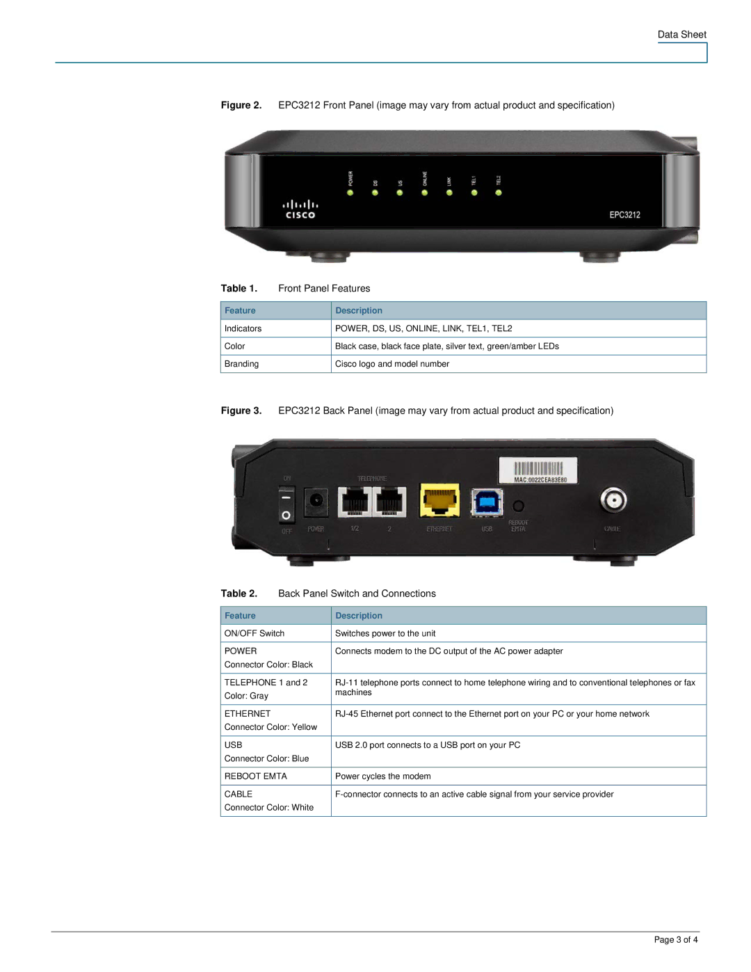
Figure 2. EPC3212 Front Panel (image may vary from actual product and specification)
Table 1. | Front Panel Features | |
|
|
|
Feature |
| Description |
Indicators |
| POWER, DS, US, ONLINE, LINK, TEL1, TEL2 |
|
|
|
Color |
| Black case, black face plate, silver text, green/amber LEDs |
|
|
|
Branding |
| Cisco logo and model number |
|
|
|
Figure 3. | EPC3212 Back Panel (image may vary from actual product and specification) | |
Table 2. | Back Panel Switch and Connections | |
|
|
|
Feature |
| Description |
ON/OFF Switch | Switches power to the unit | |
|
|
|
POWER |
| Connects modem to the DC output of the AC power adapter |
Connector Color: Black |
| |
|
| |
TELEPHONE 1 and 2 | ||
Color: Gray |
| machines |
|
| |
|
|
|
ETHERNET |
| |
Connector Color: Yellow |
| |
|
|
|
USB |
| USB 2.0 port connects to a USB port on your PC |
Connector Color: Blue |
| |
|
| |
REBOOT EMTA | Power cycles the modem | |
|
|
|
CABLE |
| |
Connector Color: White |
| |
|
|
|
Page 3 of 4