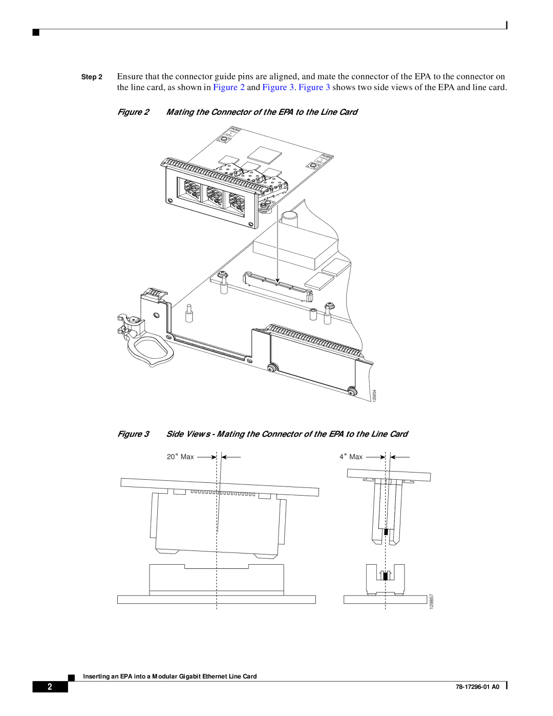
Step 2 Ensure that the connector guide pins are aligned, and mate the connector of the EPA to the connector on the line card, as shown in Figure 2 and Figure 3. Figure 3 shows two side views of the EPA and line card.
Figure 2 Mating the Connector of the EPA to the Line Card
PUSH
CORNERS
TO
INSTALL
PUSH
CORNERS
TO
INSTALL
129854
Figure 3 Side Views - Mating the Connector of the EPA to the Line Card
20˚ Max |
|
|
| 4˚ Max |
|
|
129857
Inserting an EPA into a Modular Gigabit Ethernet Line Card
2 |
| |
|
