Chapter 20 Connecting T3/E3 Network Modules
Connecting T3/E3 Network Modules to the Network
Connecting T3/E3 Network Modules to the Network
To connect a T3/E3 network module to the network, use a
Warning This equipment contains a ring signal generator (ringer), which is a source of hazardous voltage. Do not touch the
Warning If the symbol of suitability with an overlaid cross appears above a port, you must not connect the port to a public network that follows the European Union standards. Connecting the port to this type of public network can cause severe injury or damage your router. Statement 1031
Caution To minimize transient surges, the internal wiring should not be routed in the same conduit with power lines or external telephone lines.
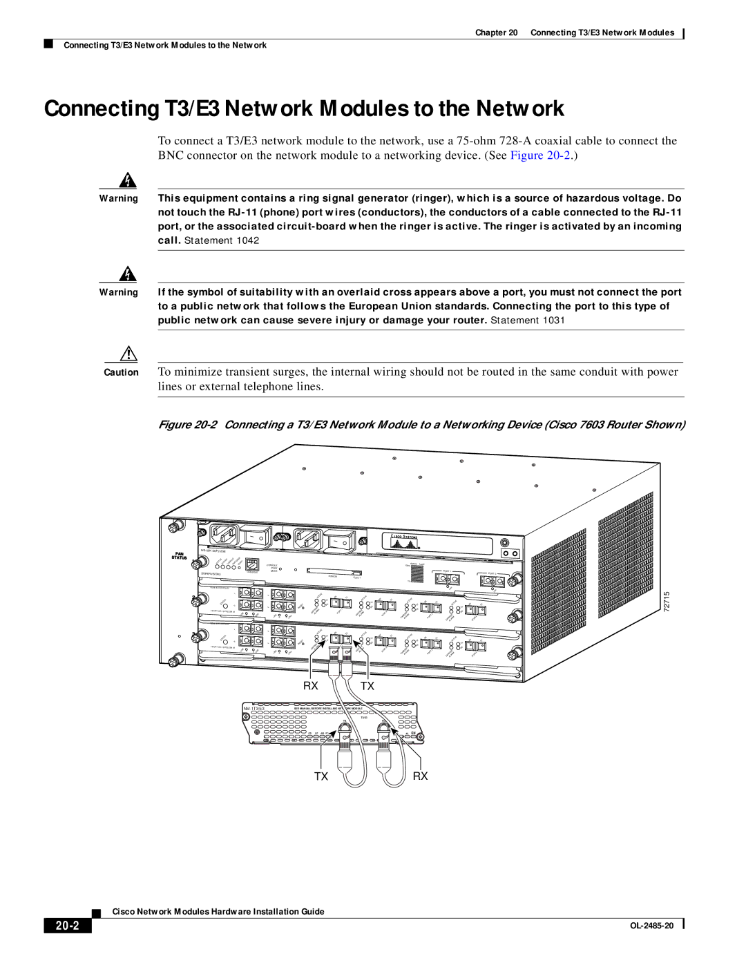
Figure 20-2 Connecting a T3/E3 Network Module to a Networking Device (Cisco 7603 Router Shown)
|
|
|
|
|
|
|
|
|
|
|
| ||
|
| MGMT |
|
|
| CONSOLE |
|
|
|
|
|
|
|
STATUS | SYSTEMCONSOLEPWR RESET |
|
|
|
|
|
|
|
|
|
| ||
|
|
|
|
|
|
|
|
|
|
|
|
| |
|
|
|
|
|
| PORT |
|
|
|
|
|
|
|
SUPERVISOR2 |
|
|
| CONSOLE | MODE |
|
|
|
|
|
|
| |
|
|
|
|
|
|
|
|
|
|
| |||
|
|
|
|
|
|
|
|
|
| PCMCIA |
|
| |
|
|
|
|
|
|
|
|
|
|
|
|
| |
|
|
|
|
|
|
|
|
|
|
|
| ||
|
| 1 |
|
|
|
|
|
|
| ACTIVE | RX |
| TX |
|
|
|
|
|
| 3 |
|
|
|
| |||
STATUS |
|
|
|
|
|
|
|
|
| TX |
|
| |
2 |
|
|
| 4 |
|
| RESET |
| RX |
| 1 | ||
|
|
|
|
|
|
|
| CARRIERALARM |
| PORT | |||
4 PORT |
|
|
|
|
|
|
|
|
| ||||
|
| LINK | 1 | 2 | LINK | LINK | 3 | 4 | LINK |
|
|
|
|
|
|
|
|
|
|
|
|
|
| ||||
|
|
|
|
|
|
|
|
|
|
|
| ||
|
| 1 |
|
|
|
|
|
|
| ACTIVE | RX |
|
|
|
|
|
|
|
| 3 |
|
|
|
|
| ||
STATUS |
|
|
|
|
|
|
|
|
| TX |
|
| |
2 |
|
|
| 4 |
|
| RESET |
| RX |
| 1 | ||
|
|
|
|
|
|
|
| CARRIERALARM |
| PORT | |||
4 PORT |
|
|
|
|
|
|
|
|
| ||||
|
| LINK | 1 | 2 | LINK | LINK | 3 | 4 | LINK |
|
|
|
|
|
|
|
|
|
|
|
|
|
| ||||
|
|
|
|
| Switch | Load |
|
|
|
|
|
|
|
|
|
| 100% |
|
|
|
|
|
|
|
|
|
|
|
|
|
|
|
| PORT 1 | PORT 2 |
|
|
|
|
|
|
|
|
|
|
| |
EJECT |
|
|
|
|
|
|
|
|
|
|
|
|
|
|
|
| 1% |
|
|
|
|
|
|
|
|
|
|
|
|
|
|
|
| LINK | LINK |
|
|
|
|
|
|
|
|
|
|
| |
ACTIVE | RX |
|
| TX | ACTIVE | RX |
|
| TX | ACTIVE |
|
TX |
|
|
|
|
|
| RX | ||||
RX |
|
|
|
| TX |
|
|
|
| ||
|
|
|
| RX |
|
|
|
|
| TX | |
CARRIERALARM |
| PORT | 2 |
|
|
|
|
|
| RX | |
|
| CARRIERALARM |
| PORT | 3 |
|
| ||||
|
|
|
|
|
|
|
|
|
| CARRIERALARM | PORT4 |
ACTIVE | RX |
|
|
| ACTIVE | RX |
|
|
| ACTIVE |
|
TX |
|
|
|
|
|
|
| RX | |||
RX |
|
|
|
| TX |
|
|
|
| ||
|
|
|
| RX |
|
|
|
|
| TX | |
CARRIERALARM |
| PORT | 2 |
|
|
|
|
|
| RX | |
|
| CARRIERALARM |
| PORT | 3 |
|
| ||||
|
|
|
|
|
|
|
|
|
| CARRIERALARM | PORT4 |
72715
RX TX
SEE MANUAL BEFORE INSTALLING NETWORK MODULE |
| T3/E3 |
TX | RX |
CD LP AIS FERF/RAI
AL EN
TXRX
Cisco Network Modules Hardware Installation Guide
|
| |
|