Diagnostics
B
5Diagnostics
Diagnostics are displayed on the
•Checking error states and signal integrity
•Identifying the cable terminal on the network
•Verifying communications with the headend For the diagnostics described in this section:
•All indicators are in decimal notation, unless otherwise noted.
•All
•All sample displays are illustrative; actual data may differ from the examples.
Using the Diagnostics
To use the diagnostics:
1.Ensure that the
2.Ensure the
3.Press power to put the
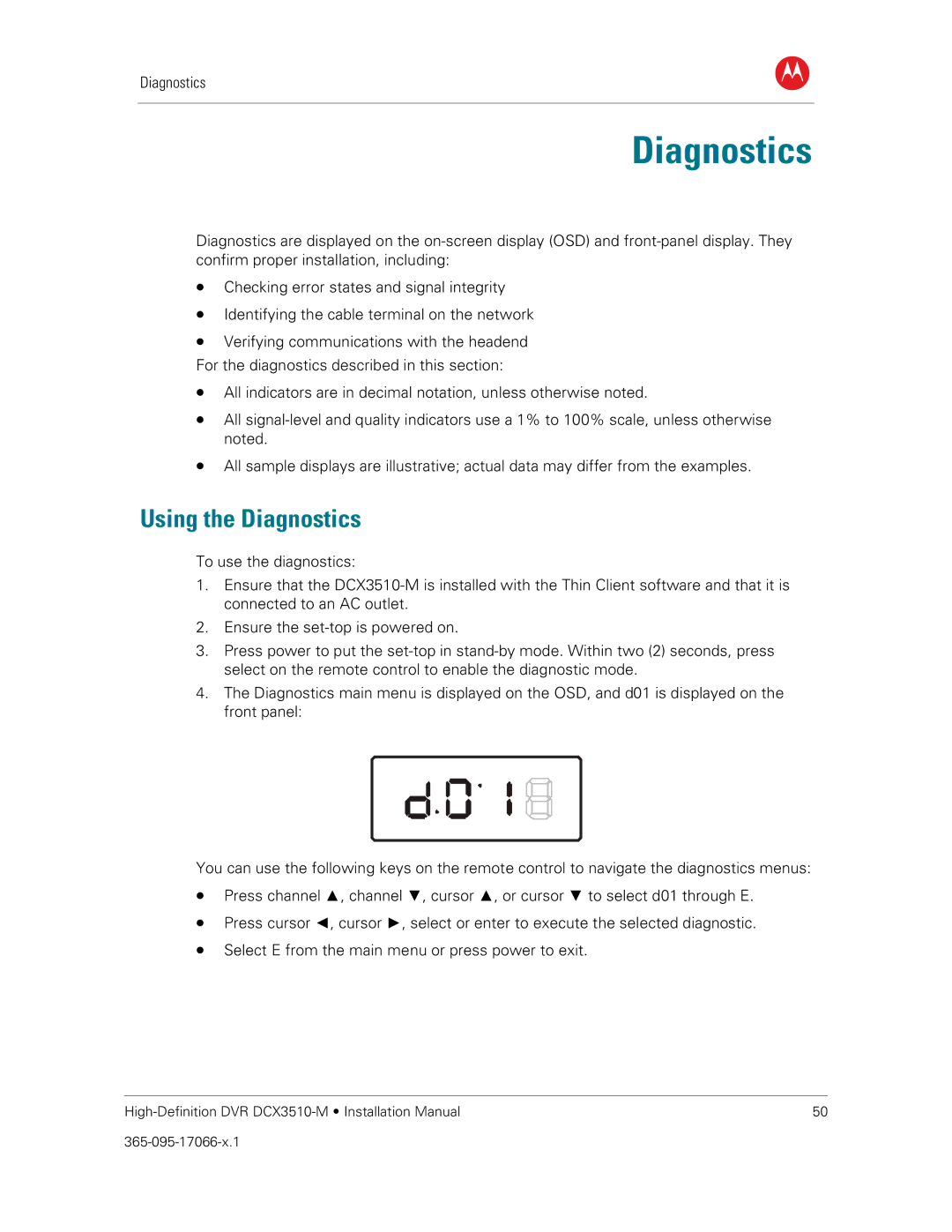
4.The Diagnostics main menu is displayed on the OSD, and d01 is displayed on the front panel:
You can use the following keys on the remote control to navigate the diagnostics menus:
•Press channel ▲, channel ▼, cursor ▲, or cursor ▼ to select d01 through E.
•Press cursor ◄, cursor ►, select or enter to execute the selected diagnostic.
•Select E from the main menu or press power to exit.
50 |