QUICK START GUIDE
Installing Cisco
and
Line Cards
1Purpose
2Feature Description
3Prerequisites
4Installing the Card
5Removing the Card
6Troubleshooting
7Technical Specifications
8Related Documentation
Warning | Only trained and qualified |
| personnel should be allowed to |
| install, replace, or service this |
| product; and should be properly |
| grounded before handling this |
| |
|
|
1Purpose
This quick start guide shows you how to install a Cisco
2Feature Description
The Cisco
•Cisco
•Cisco
•Cisco
3Prerequisites
•The Cisco
•If you are replacing a Cisco
4Installing the Card
Note The
Step 1 Make sure that you are grounded.
Step 2 Use both hands to grasp the card by its metal carrier edges and align the card with the slot guides, component side up.
Step 3 With the metal carrier aligned in the slot guides (see Figure 1), gently slide the card into the card slot until you can feel it seated in the backplane connectors.
Step 4 Tighten the captive screws.
Note The captive screws provide grounding for the electromagnetic interference (EMI) shielding.
Figure 1 Installing the Card in the Chassis
88984
US0 | US1 | US2 | US3 | US5 | US6 | US7 | uBR - MC28U | DS0- | DS1- |
| RF | RF |
Note The cable interface line card insertion/removal method is the same for all Cisco uBR7200 series routers.
Cabling
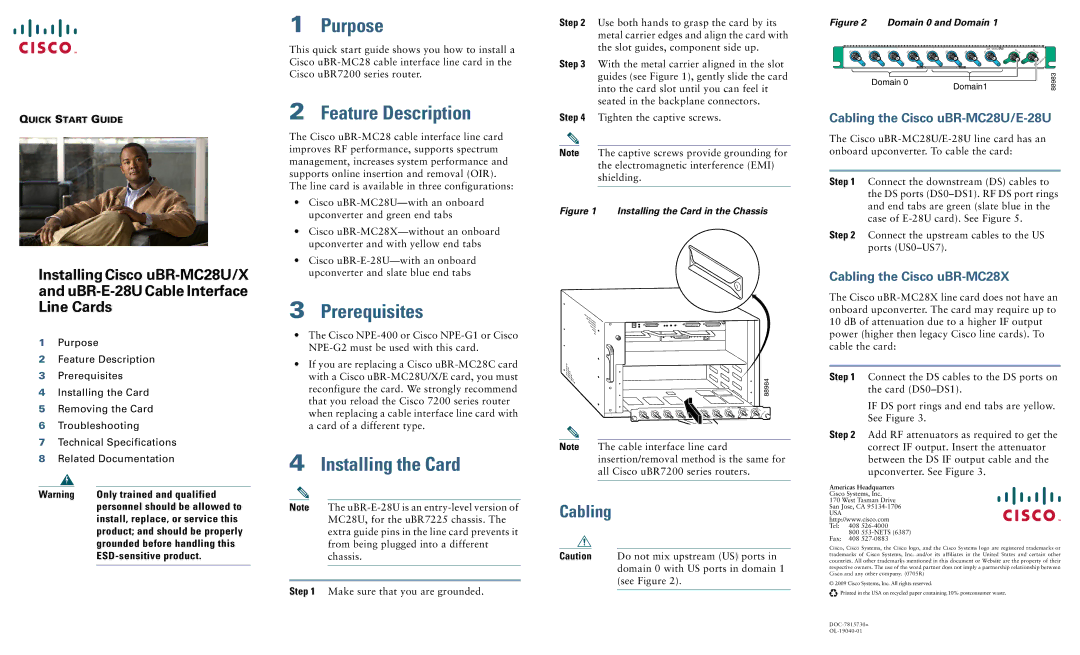
Caution Do not mix upstream (US) ports in domain 0 with US ports in domain 1 (see Figure 2).
Figure 2 Domain 0 and Domain 1
|
|
|
|
|
|
| uBR - MC28U | DS0- | DS1- | |
US0 | US1 | US2 | US3 | US4 | US5 | US6 | US7 | |||
RF | RF | |||||||||
|
|
|
|
|
|
|
|
| ENABLED | |
|
| Domain 0 |
|
| Domain1 |
| 88983 | |||
Cabling the Cisco uBR-MC28U/E-28U
The Cisco
Step 1 Connect the downstream (DS) cables to the DS ports
Step 2 Connect the upstream cables to the US ports
Cabling the Cisco uBR-MC28X
The Cisco
Step 1 Connect the DS cables to the DS ports on the card
IF DS port rings and end tabs are yellow. See Figure 3.
Step 2 Add RF attenuators as required to get the correct IF output. Insert the attenuator between the DS IF output cable and the upconverter. See Figure 3.
Americas Headquarters
Cisco Systems, Inc.
170 West Tasman Drive San Jose, CA
USA http://www.cisco.com Tel: 408
800
Fax: 408
Cisco, Cisco Systems, the Cisco logo, and the Cisco Systems logo are registered trademarks or trademarks of Cisco Systems, Inc. and/or its affiliates in the United States and certain other countries. All other trademarks mentioned in this document or Website are the property of their respective owners. The use of the word partner does not imply a partnership relationship between Cisco and any other company. (0705R)
© 2009 Cisco Systems, Inc. All rights reserved.
![]()
![]() Printed in the USA on recycled paper containing 10% postconsumer waste.
Printed in the USA on recycled paper containing 10% postconsumer waste.