Front Panel Description
Status LED
At startup, the CSM initializes various hardware components and communicates with the supervisor engine. The Status LED indicates the supervisor engine operations and the initialization results. During the normal initialization sequence, the status LED changes from off to red, orange, and green.
Note For more information on the supervisor engine LEDs, refer to the Catalyst 6500 Series Switch Module Installation Guide.
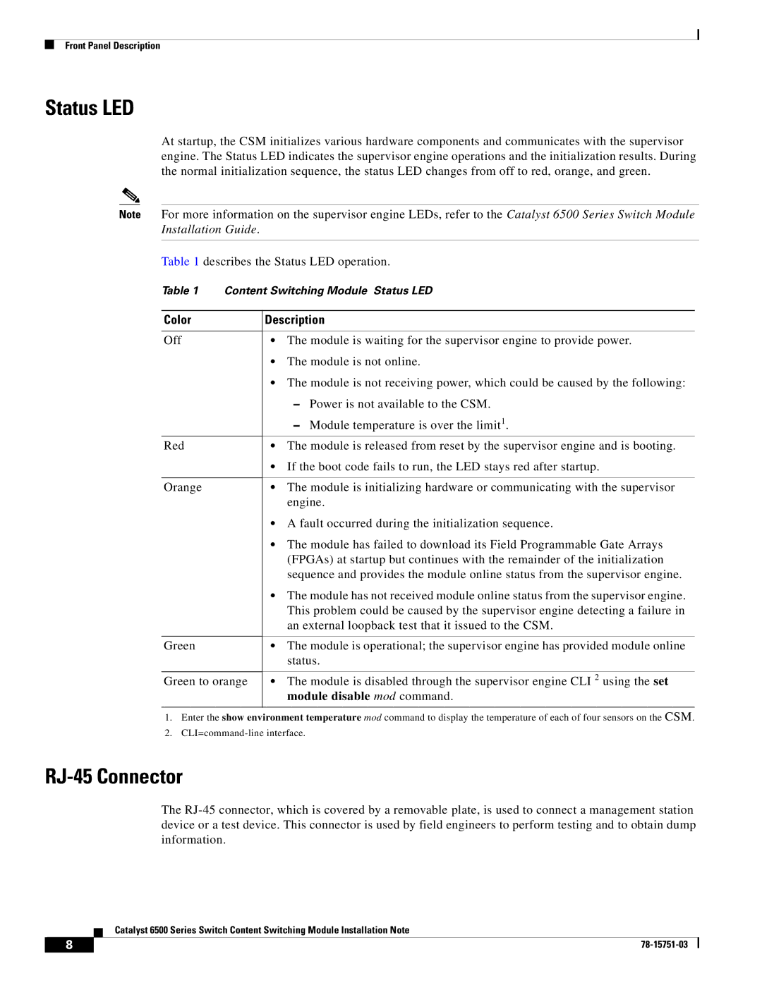
Table 1 describes the Status LED operation.
Table 1 Content Switching Module Status LED
Color
Off
Red
Orange
Green
Green to orange
Description
•The module is waiting for the supervisor engine to provide power.
•The module is not online.
•The module is not receiving power, which could be caused by the following:
–Power is not available to the CSM.
–Module temperature is over the limit1.
•The module is released from reset by the supervisor engine and is booting.
•If the boot code fails to run, the LED stays red after startup.
•The module is initializing hardware or communicating with the supervisor engine.
•A fault occurred during the initialization sequence.
•The module has failed to download its Field Programmable Gate Arrays (FPGAs) at startup but continues with the remainder of the initialization sequence and provides the module online status from the supervisor engine.
•The module has not received module online status from the supervisor engine. This problem could be caused by the supervisor engine detecting a failure in an external loopback test that it issued to the CSM.
•The module is operational; the supervisor engine has provided module online status.
•The module is disabled through the supervisor engine CLI 2 using the set module disable mod command.
1.Enter the show environment temperature mod command to display the temperature of each of four sensors on the CSM.
2.
RJ-45 Connector
The
Catalyst 6500 Series Switch Content Switching Module Installation Note
8 |
| |
|
