2003/1 (AB·C)

284-9753-00

Installation/Wire Connection Guide ￿￿/ ￿￿/￿￿=

English

￿￿


1.


BEFORE STARTING /


/


1.

This set is exclusively for use in cars with a

1.

12V

1.

￿=

=12VI=åÉÖ~íáîÉ=ÖêçìåÇ￿=￿￿


negative ground, 12 V power supply.

￿￿


=￿￿=

=


K


2.

Read these instructions carefully.

2.


2.

￿=


=￿￿=￿￿=


K


3.

Be sure to disconnect the battery “v” terminal

3.

v

3.


=

=

=“v


=￿￿


before starting. This is to prevent short circuits


1F


K=

=

=

=

=￿


during installation. (Figure 1)


￿￿=

K=E￿￿=1F


Figure 1 / ￿ 1 / ￿￿ 1


English

￿￿


2.


CAUTIONS ON INSTALLATION /


/

=


1.

Prepare all articles necessary for installing the source unit before

1.


1.


=￿￿= =

=


=￿￿=


K


starting.


2.


30°


E￿2F


2.

=

=30°=

=


K=E￿￿=2F


2.

Install the unit within 30° of the horizontal plane. (Figure 2)


3.


3.

=

=￿￿=￿￿=￿￿=

=

=￿￿I=

=￿=￿

3.

If you have to do any work on the car body, such as drilling holes,


4.


E￿3F


￿￿=


K


consult your car dealer beforehand.


4.


4.

Use the enclosed screws for installation. Using other screws can


=

=

=


K=￿￿=

=

=￿

Fixed Mount

(TOYOTA, NISSAN and other ISO/DIN equipped vehicles)

This unit is designed for fixed installation in the dashboard.

If the vehicle is equipped with a factory-installed radio, install the source unit with the parts and screws marked (). (Figure 9)

If the vehicle is not equipped with a factory-installed radio, obtain an installation kit to install the source unit in the following procedure.

Remove the stopper following the procedures below.

1.Remove the screw from the source unit (Figure 6).

2.Remove the stopper from the source unit (Figure 7).

3.Install the remove screw to the source unit (Figure 8).

Securely attach the screw.

Note: Store the removed stopper in a safe place together with the Instruction Manual.

ISO/DIN

■ ￿￿=￿￿


E

F

E


I=￿￿=

=fplLafk=

=￿￿=

F


￿=￿￿￿=


=￿￿=

= =

=


K=￿￿=￿￿=

=


EF

￿=

=


I=￿=￿￿=EF￿=￿￿=

=

=

=

K

￿￿ 9￿


E￿￿ 9F


￿￿=

=


=

=￿￿=

I=￿￿=


= =

=￿￿=￿￿


￿=

=


K


1.

6￿￿


=


=￿￿=

=

K


1.


K=E￿￿ 6F


2.

7￿￿


=

=


2.


K=E￿￿ 7F


3.

8￿￿


=


=


3.


K=E￿￿ 8F


=


=

=


=￿￿￿=


K


￿￿:


￿:


=


=


=￿￿=

=

=

K


cause damage. (Figure 3)

￿= =￿￿=￿=

K=E￿￿=3F


Figure 2 / ￿ 2 / ￿￿ 2Figure 3 / ￿ 3 / ￿￿ 3

English ￿￿


3. INSTALLING THE SOURCE UNIT /

/ ￿￿=￿￿

4.

Secure the mounting brackets to the chassis as shown in Figure 9. Holes are pre-

4.

￿￿9

4.

￿￿ 9￿=

=￿￿=￿￿=￿￿=

=

=

K=

=￿￿=￿


tapped for TOYOTA and NISSAN vehicles; modification, such as drilling new holes, of


= =

=

=

X=￿￿=￿￿=

=￿￿I=￿￿=


the mounting brackets may be required for other models.

5.

￿￿6


￿￿=￿=￿￿=

=

=

=￿￿=

K


5.

Wire as shown in Section 6.

5.

￿￿ 6￿=

=￿￿=￿￿=

= K


6.


6.

Secure the unit in the dashboard, and then reassemble the dashboard and the center


6.

=

=

=￿￿I=

=￿￿=

=￿￿=


K


panel.

Universal Mount

1.Place the universal mounting bracket into the instrument panel, use a screwdriver to bend each stopper of the universal mounting bracket inward, t-hen secure the stopper as shown in Figure 4.

2.Wire as shown in Section 6.

3.Insert the source unit into the universal mounting bracket until it locks.

4.Take care of the top and bottom of the outer escutcheon and mount it so that all the hooks are locked. (Figure 5)

Notes:

1)Some car models require special mounting kits for proper installation. Consult your Clarion dealer for details.

2)Fasten the front stopper securely to prevent the source unit from coming loose.

1.

4

2.￿￿6

4.

E￿ 5F

￿￿


1)

Clarion￿

2)


￿￿=￿￿

1.

￿￿=

=


=

=￿￿=￿￿I=

=￿￿=


=

=￿￿=

=

=￿￿=4￿￿=￿￿=￿￿


￿￿=


=


K


2.

￿￿=6￿=

=￿￿=￿￿=

=

K


3.


=￿￿=


=￿￿=

=

K


4.

￿￿=


=￿=

=

=

=￿￿=

=


￿￿K=E￿￿ 5F


￿W


1) ￿=

=￿￿I=

=

= =

=￿￿=

=￿￿


￿=￿￿=

K=

=￿￿=`ä~êáçå￿= =

K

2)

=

=￿￿￿=

=

=

=￿￿=￿￿


K


: The parts and SCREW with this mark are used to install radio or included in the

:


: ￿=

=

=

=

=

=

=

I=￿￿=


=

installation kit.

:


K


: The screws with this mark are originally attached to the vehicle.

￿1￿

E

F￿

: ￿=

=

=

=

=

=


=￿￿=

K


Note 1: In some cases, the center panel may require some modification (trimming, filling,

￿2￿


￿=1

:

=


=￿￿=

=￿￿=

=

=

K=E￿￿I=￿￿=￿F

etc.).


￿=2

: ￿￿=


=￿￿=￿￿=

=

=￿￿I=

=￿￿=

=

=￿

Note 2: If a hook on the installation bracket interferes with the unit, bend and flatten it


=


K


with a nipper or a similar tool.


English

￿￿


4.


REMOVAL OF THE SOURCE UNIT /


/ ￿￿=￿￿


1.

When removing the source unit, disassemble it in the reverse of the order in

1.

3￿￿3.

1.

=

=￿￿I=￿￿=“3. ￿￿=￿￿”=￿=

=

K


Section “3. INSTALLING THE SOURCE UNIT”.

2.

EDCPF￿

2.

=

=￿￿EDCPF￿=

K


2.

Remove the Detachable Control Panel (DCP).

EDCPF


DCP=

=￿￿=

=￿￿=

=


K


For instructions on removing the DCP, refer to the owner’s manual.

3.


10￿

3.

￿￿=

=

= =

K=E￿￿ 10F


3.

Press the outer escutcheon upward and remove it. (Figure 10)


4.

=￿￿ 11￿

4.

￿=

=￿￿=

K=E￿￿ 11F


4.

Insert and lock the hook plates. (Figure 11)


5.


5.

￿=

= =

=

K


5.

Pull the hook plates to remove the source unit.


Figure 5 / ￿ 5 / ￿￿=5


English

￿￿


5.


CAUTIONS ON WIRING /


/

=


1.

Be sure to turn the power off when wiring.

1.


1.


=￿=￿￿=

=

=￿=


K


2.

Be particularly careful where you route the wires. Keep them well away from the

2.


2.


=￿￿=

=￿￿=

=


K=

=￿￿I=

=


engine, exhaust pipe, etc. Heat may damage the wires.


￿=

=

=￿￿=￿￿I=￿￿=￿￿=

=￿￿=


=￿￿=

K

3.

If the fuse should blow, check that the wiring is correct. If it is, replace the fuse

3.


3.


=

=￿￿I=

=


=￿￿=

=


K=

=


with a new one with the same amperage rating as the original one.


I=

=

=￿￿=


=

=￿=

=

=

K

4.

To replace the fuse, open the lock on the source unit side, remove the old fuse and

4.


12￿

4.


=

=￿￿=


=

=￿￿= =

=

=￿=￿￿=


insert the new one. (Figure 12)


￿K=E￿￿ 12F


There are various types of fuse cases. Do not let the battery side terminal touch

5.

CeNET


=￿￿=

=

K=


=￿￿=

=￿￿=￿￿=

=￿￿


other metal parts.


=

K


CeNET


5.

Connect the CeNET extension cable fully and securely until it locks. When the


￿CeNET


CCA-520￿8￿￿E2K5￿F￿￿

5. CeNET=￿￿=


=

=

=￿￿￿=

=

=

K


CeNET extension cable is pulled, hold the slide cap part and pull it towards you.


CCA-521￿2￿￿E0.6￿F

Y

CCA-519


CeNET=￿￿=


=

=

I=

=￿=


=￿￿=

=￿￿


When the CeNET extension cable is extended or branches, use extension cable


￿￿Clarion

CeNET


K


CCA-520 (8 feet [2.5m]) or CCA-521 (2 feet [0.6m]), or Y-adapter CCA-519


CeNET=￿￿=

=￿￿=￿￿=

=￿￿=￿￿=


=CCA-520E8=￿￿


(each of them is sold seperately).


x2.5mzF=￿￿=CCA-521E2￿￿x0.6mzF=￿￿=vJ

=CCA-519￿=

=￿￿


Use the CeNET extension cable made by Clarion.


￿￿K=E￿￿=￿￿F


Clarion￿￿=CeNET=￿￿=


=

K


Figure 4 / ￿ 4 / ￿￿=4

Page 1
Image 1
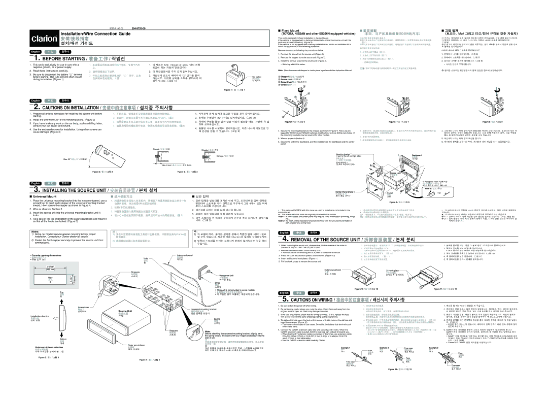
Clarion DXZ835MP instruction manual Before Starting, Installing the Source Unit, Removal of the Source Unit, Fixed Mount

DXZ835MP specifications

The Clarion DXZ835MP is a versatile and high-performing car audio receiver designed to enhance the in-car listening experience. With its sleek design and array of features, it has become a popular choice among car enthusiasts who prioritize sound quality and functionality.

One of the main features of the DXZ835MP is its powerful playback capabilities. This receiver supports a variety of media formats, including MP3, WMA, and AAC, allowing users to enjoy their favorite music in various formats. The front-panel USB port and AUX input provide easy access to digital music stored on USB drives or external devices, ensuring that users can connect their smartphones and other media players seamlessly.

The DXZ835MP is equipped with a built-in four-channel amplifier that delivers impressive audio performance. With an output of 50 watts per channel, this receiver provides ample power to drive speakers effectively. Additionally, the unit features a 3-band parametric equalizer, enabling users to fine-tune the audio settings to their preferences and achieve optimal sound quality in different environments.

Another standout feature of the Clarion DXZ835MP is its advanced radio capabilities. The receiver features a built-in AM/FM tuner with 18 preset stations, ensuring that drivers can easily access their favorite radio stations. The DXZ835MP also supports RDS (Radio Data System), which provides additional information about the broadcast, including station names and current song titles.

Technology-wise, the DXZ835MP incorporates a variety of modern enhancements. The unit is compatible with Clarion's proprietary iPod connectivity interface, which allows users to control their iPods directly from the receiver's interface. This compatibility makes it convenient to browse playlists and select tracks without having to use the device itself. Furthermore, the receiver features a detachable faceplate, providing an added layer of security against theft.

In terms of build quality, the DXZ835MP is designed to withstand the rigors of daily use. The robust construction ensures durability, while the clear LCD display provides easy visibility even in bright environments. Overall, the Clarion DXZ835MP is an impressive car audio receiver packed with features, making it an excellent choice for those looking to upgrade their in-car entertainment system. With its combination of sound quality, connectivity, and user-friendly interface, the DXZ835MP remains a top contender among car audio receivers.