VMA633 6.5” TFT LCD Monitor
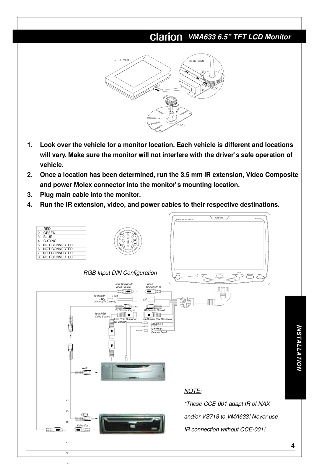
1.Look over the vehicle for a monitor location. Each vehicle is different and locations will vary. Make sure the monitor will not interfere with the driver’s safe operation of vehicle.
2.Once a location has been determined, run the 3.5 mm IR extension, Video Composite and power Molex connector into the monitor’s mounting location.
3.Plug main cable into the monitor.
4.Run the IR extension, video, and power cables to their respective destinations.
1 | RED |
|
|
|
2 | GREEN | 4 | 2 | 5 |
3 | BLUE |
| ||
1 |
| 3 | ||
4 | 8 | |||
5 | NOT CONNECTED | 6 |
| 7 |
6 | NOT CONNECTED |
|
|
|
7 | NOT CONNECTED |
|
|
|
8 | NOT CONNECTED |
|
|
|
RGB Input DIN Configuration
6.5 INCH WIDE LCD MONITOR | VMA633 |
| from Composite | Video |
| Video Source | Composite In |
To lgnition | Fuse |
|
+12V |
|
|
Ground(To Chassis) |
| |
| To Remote Onput | IR Remote Output |
from RGB |
|
|
Video Source | from RGB Output of | RGB Input DIN Connector |
| ||
| NAX9500E | |
|
| |
|
| speaker(+) |
|
| Dimmer Lead |
NAX
*
C
C
VS718
E
Video Out
-
0
NOTE:
*These
and/or VS718 to VMA633! Never use
IR connection without
NSTALLATION
4
0
1