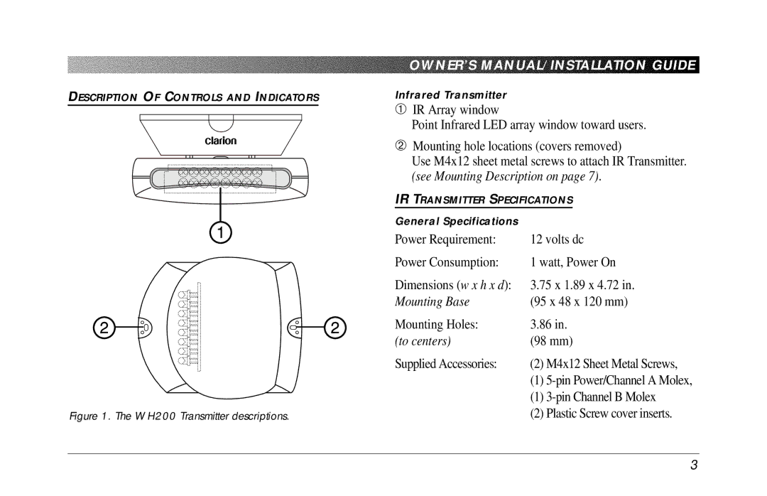
DESCRIPTION OF CONTROLS AND INDICATORS
Figure 1. The WH200 Transmitter descriptions.
OWNER’S MANUAL/INSTALLATION GUIDE
Infrared Transmitter
1IR Array window
Point Infrared LED array window toward users.
2Mounting hole locations (covers removed)
Use M4x12 sheet metal screws to attach IR Transmitter. (see Mounting Description on page 7).
IR TRANSMITTER SPECIFICATIONS
General Specifications |
|
Power Requirement: | 12 volts dc |
Power Consumption: | 1 watt, Power On |
Dimensions (w x h x d): | 3.75 x 1.89 x 4.72 in. |
Mounting Base | (95 x 48 x 120 mm) |
Mounting Holes: | 3.86 in. |
(to centers) | (98 mm) |
Supplied Accessories: | (2) M4x12 Sheet Metal Screws, |
| (1) |
| (1) |
| (2) Plastic Screw cover inserts. |
3