Assembly
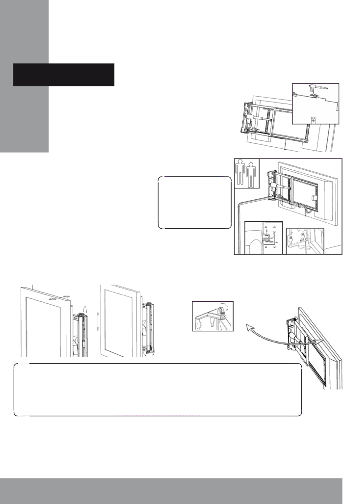
5. Fix the central unit and connect the actuator. Con- nect also the external IR eye and powersupply temporar- ily. Press the enclosed remote to open the mount fully. Disconnect and remove the powersupply and IR eye.
6. Lift up the
the actuator from the bracket. Mount the addi- | ! Depending on wall |
tional screws in the wall. Assembly the actuator | surface IR reflection |
again. Connect all cables for the TV and also the | factor, the remote re- |
powersupply and IR eye to the wall mount. Wire | ceiver may require clear |
them to the frame with the enclosed cable ties. | sight from IR remote |
Pay attention to that no cables get stuck in the |
|
mechanism when operating. Fasten also the soft |
|
stopper pad as illustrated. |
|
7. If necessary, use the smart horizontal and vertical adjustments to align the wall mount in level.
8. Carefully adjust the friction brake for smooth operation. (Normally not necessary).
!If the TV turns out to be very slanting, or the wallmount does not fully close, you need to adjust the
4 English | MADE IN SWEDEN |
