Operation (Cont.)
13. CH.19/CH.9/NORMAL SWITCH. Used for instant selection of emer- gency Channel 9 (CH. 9 position) or information Channel 19. In NOR- MAL position, all 40 CB channels are selected by the CHANNEL SELEC- TOR switch (8).
14.
SWR METER. Measures standing wave ratio of the antenna system. Used to properly adjust the length of the antenna and to monitor the quality of the coaxial cable and all RF electrical connections. If there is any degradation whatsoever in any of the foregoing, due to humidity, salt spray, vibration or corrosion, the SWR meter reading will rise, thereby indicating that a problem exists.
To calibrate, switch to the "CAL" position, transmit by pressing the mike switch, and adjust the SWR control to the "CAL" mark on the meter; then switch to "SWR" position for the SWR measurement.
15. RX/TX LED INDICATOR. When your radio is in the CB receive mode, the LED will be green. When in transmit mode, the LED will be red.
16. SOUNDTRACKER™ SWITCH. Depressing this button turns on the SoundTracker system in your CB.
17. SOUNDTRACKER™ INDICATOR. A red LED will illuminate when the SoundTracker system is engaged on your CB.
18. LED CHANNEL DISPLAY. The selected channel will be displayed.
B.
10
Operation (Cont.)
3 | 1 | 2 |
4
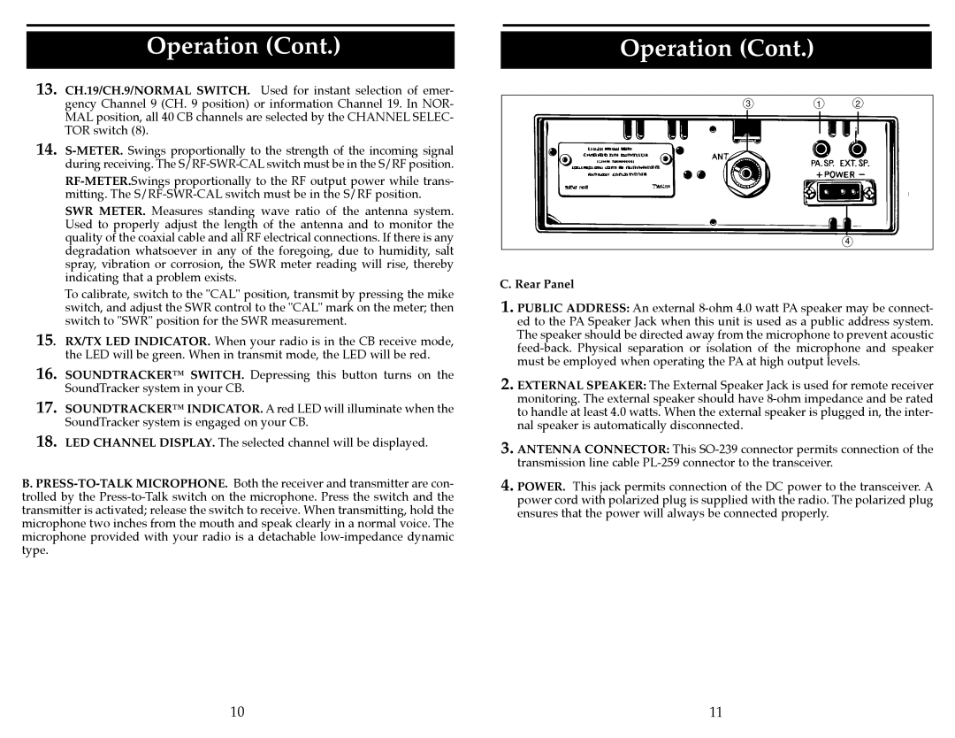
C. Rear Panel
1. PUBLIC ADDRESS: An external
2. EXTERNAL SPEAKER: The External Speaker Jack is used for remote receiver monitoring. The external speaker should have
3. ANTENNA CONNECTOR: This
4. POWER. This jack permits connection of the DC power to the transceiver. A power cord with polarized plug is supplied with the radio. The polarized plug ensures that the power will always be connected properly.
11