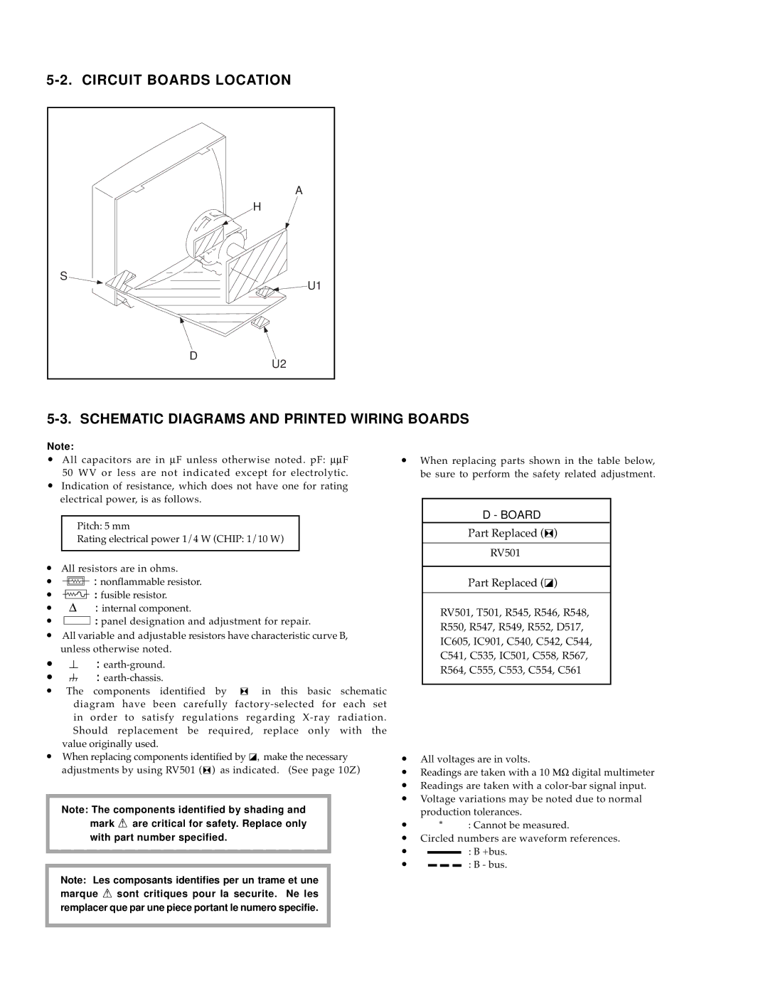
A
H
S
![]() U1
U1
D
U2
Note:
•All capacitors are in μF unless otherwise noted. pF: μμF 50 WV or less are not indicated except for electrolytic.
•Indication of resistance, which does not have one for rating electrical power, is as follows.
Pitch: 5 mm
Rating electrical power 1/4 W (CHIP: 1/10 W)
•All resistors are in ohms.
•f : nonflammable resistor.
•F : fusible resistor.
•Δ : internal component.
•p : panel designation and adjustment for repair.
•All variable and adjustable resistors have characteristic curve B, unless otherwise noted.
•e :
• E :
•The components identified by [ in this basic schematic diagram have been carefully
in order to satisfy regulations regarding
value originally used.
•When replacing components identified by ], make the necessary adjustments by using RV501 ([) as indicated. (See page 10Z)
Note: The components identified by shading and mark Á are critical for safety. Replace only
with part number specified.
Note: Les composants identifies per un trame et une marque Á sont critiques pour la securite. Ne les remplacer que par une piece portant le numero specifie.
•When replacing parts shown in the table below, be sure to perform the safety related adjustment.
D - BOARD
Part Replaced ([)
RV501
Part Replaced (])
RV501, T501, R545, R546, R548,
R550, R547, R549, R552, D517,
IC605, IC901, C540, C542, C544,
C541, C535, IC501, C558, R567,
R564, C555, C553, C554, C561
•All voltages are in volts.
•Readings are taken with a 10 ΜΩ digital multimeter
•Readings are taken with a
•Voltage variations may be noted due to normal production tolerances.
•* : Cannot be measured.
•Circled numbers are waveform references.
•: B +bus.
•![]()
![]()
![]() : B - bus.
: B - bus.