Manufacturer’s Specifications | Measured in the ARRL Lab |
FM adjacent channel rejection: Not specified. | 20 kHz offset, preamp on: |
| 29 MHz, 59 dB; 52 MHz, 44 dB. |
FM | 20 kHz offset, preamp on: |
Not specified. | 29 MHz, 59 dB*; 52 MHz, 44 dB*; |
| 10 MHz offset: 52 MHz, n/a.3 |
S9 signal at 14.2 MHz: preamp off, | |
| 50 µV; preamp on, 50 µV. |
Squelch sensitivity: Not specified. | At threshold, preamp on: SSB, 14 MHz, |
| 0.28 µV; FM, 29 MHz, 0.22 µV; |
| 52 MHz, 0.6 µV. |
Audio output power: 10 dBV at 600 Ω. | As specified.4 |
IF/audio response: Not specified. | Range at |
| CW (500 Hz): |
| Equivalent Rectangular BW: 499 Hz; |
| USB: |
| LSB: |
| AM: |
Image rejection: 70 dB. | First IF rejection, 43 dB5; image |
| rejection, 88 dB. |
Transmitter | Transmitter Dynamic Testing |
Power output: HF and 50 MHz: SSB, CW, | HF: CW, SSB, FM, typically 100 W high, |
FM, 100 W (high); AM, 25 W (carrier) | <1 W low; AM, typ. 25 W high, <1 W low; |
| 50 MHz: CW, SSB, FM, typ 99 W high, |
| <1 W low; AM, typ. 25 W high, <1 W low. |
Spurious and harmonic suppression: | HF, 51 dB; VHF, 61 dB. |
HF, >55 dB; VHF, >65 dB | Meets FCC requirements. |
SSB carrier suppression: >55 dB. | HF, 51 dB; VHF, 54 dB. |
Undesired sideband suppression: >55 dB. | HF, 61 dB; VHF, 60 dB. |
3rd/5th/7th/9th order (worst case band): | |
products: | HF, |
| VHF, |
CW keyer speed range: Not specified. | 1 to 60 WPM. |
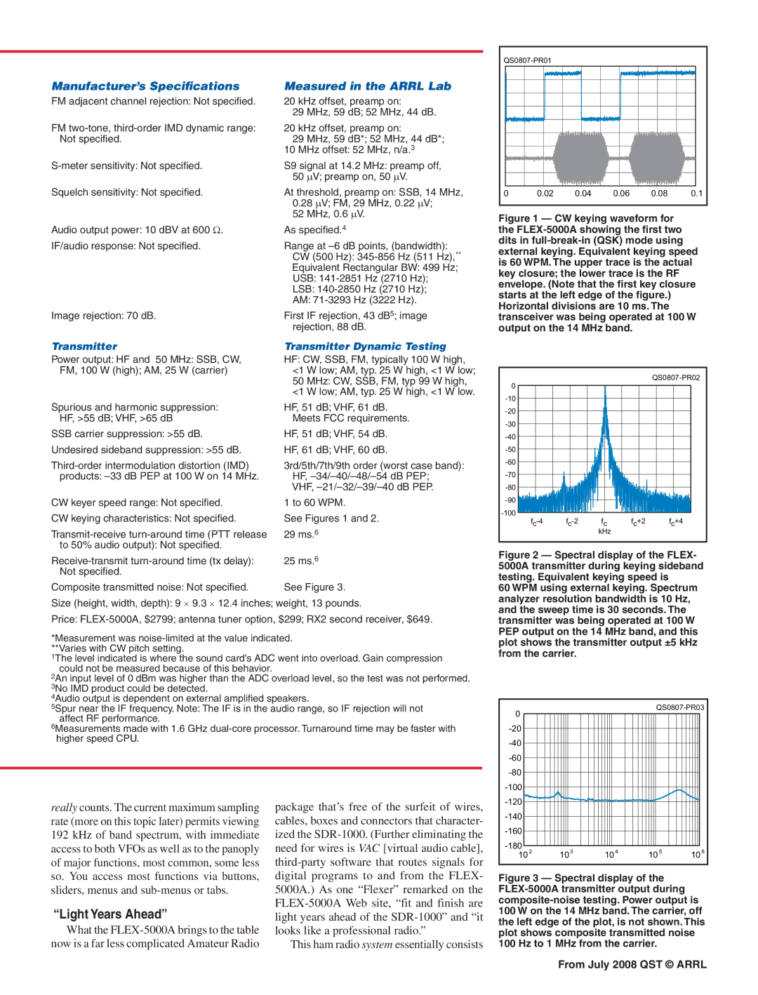
CW keying characteristics: Not specified. | See Figures 1 and 2. |
29 ms.6 | |
to 50% audio output): Not specified. |
|
25 ms.6 | |
Not specified. |
|
Composite transmitted noise: Not specified. | See Figure 3. |
Size (height, width, depth): 9 × 9.3 × 12.4 inches; weight, 13 pounds.
Price:
*Measurement was
1The level indicated is where the sound card’s ADC went into overload. Gain compression could not be measured because of this behavior.
2An input level of 0 dBm was higher than the ADC overload level, so the test was not performed. 3No IMD product could be detected.
4Audio output is dependent on external amplified speakers.
5Spur near the IF frequency. Note: The IF is in the audio range, so IF rejection will not affect RF performance.
6Measurements made with 1.6 GHz
0 | 0.02 | 0.04 | 0.06 | 0.08 | 0.1 |
Figure 1 — CW keying waveform for the FLEX-5000A showing the first two dits in full-break-in (QSK) mode using external keying. Equivalent keying speed is 60 WPM. The upper trace is the actual key closure; the lower trace is the RF envelope. (Note that the first key closure starts at the left edge of the figure.) Horizontal divisions are 10 ms. The transceiver was being operated at 100 W output on the 14 MHz band.
0 |
|
|
| |
|
|
|
| |
|
|
|
| |
|
|
|
| |
|
|
|
| |
|
|
|
| |
|
|
|
| |
|
|
|
| |
|
|
|
| |
|
|
|
| |
|
|
|
| |
|
|
|
| |
fc | fc+2 | fc+4 | ||
|
| kHz |
|
|
Figure 2 — Spectral display of the FLEX- 5000A transmitter during keying sideband testing. Equivalent keying speed is
60 WPM using external keying. Spectrum analyzer resolution bandwidth is 10 Hz, and the sweep time is 30 seconds. The transmitter was being operated at 100 W PEP output on the 14 MHz band, and this plot shows the transmitter output ±5 kHz from the carrier.
0 | |
| |
| |
| |
| |
| |
|
really counts. The current maximum sampling rate (more on this topic later) permits viewing 192 kHz of band spectrum, with immediate access to both VFOs as well as to the panoply of major functions, most common, some less so. You access most functions via buttons, sliders, menus and
“Light Years Ahead”
What the
package that’s free of the surfeit of wires, cables, boxes and connectors that character- ized the
This ham radio system essentially consists
|
|
|
|
| |
|
|
|
|
| |
|
|
|
|
| |
2 | 103 | 104 | 105 | 106 | |
10 |
Figure 3 — Spectral display of the FLEX-5000A transmitter output during composite-noise testing. Power output is 100 W on the 14 MHz band. The carrier, off the left edge of the plot, is not shown. This plot shows composite transmitted noise 100 Hz to 1 MHz from the carrier.
From July 2008 QST © ARRL
