Replacing the Burner Door Assembly
![]() WARNING
WARNING
Explosion Hazard
Tighten both manifold door screws securely.
Remove any fiberglass between gasket and combustion chamber.
Replace viewport if glass is missing or damaged.
Replace two piece wire connector if missing or removed.
Replace door gasket if damaged.
Failure to follow these instructions can result in death, explosion, or fire.
1.Check the door gasket for damage or imbedded debris prior to installation.
![]() WARNING
WARNING
Explosion Hazard
Replace viewport if glass is missing or damaged.
Failure to do so can result in death, explosion or fire.
2.Inspect the viewport for damage and replace as required.
3.Insert the burner door assembly into the combustion chamber and slide it completely forward. Note: When inserting the burner door assembly, tip the burner end up slightly to ensure it engages with the burner bracket.
4.Inspect the door gasket and make sure there is no fiberglass insulation between the door gasket and the combustion chamber (See Figure 28).
5.Replace the two screws, which secure the burner door assembly to the combustion chamber and tighten securely. Once the burner door assembly is tightened, visually inspect the door gasket between the burner door assembly and the combustion chamber for spaces or gaps that would prevent a seal. IMPORTANT: Do not operate the water heater if the door gasket does not create a seal between the burner door assembly and the combustion chamber.
6.Reconnect the manifold tubing, pilot tubing, and thermocouple to the thermostat. Do not
24
7/16” open end wrench will then be sufficient to seat the lockwasher.
7.Reconnect the igniter wire.
8.Turn gas supply on and refer to the “Lighting Instructions”.
9.Check for leaks by brushing on an approved noncorrosive leak detection solution. Bubbles will show a leak. Correct any leak found.
10.Replace the outer door.
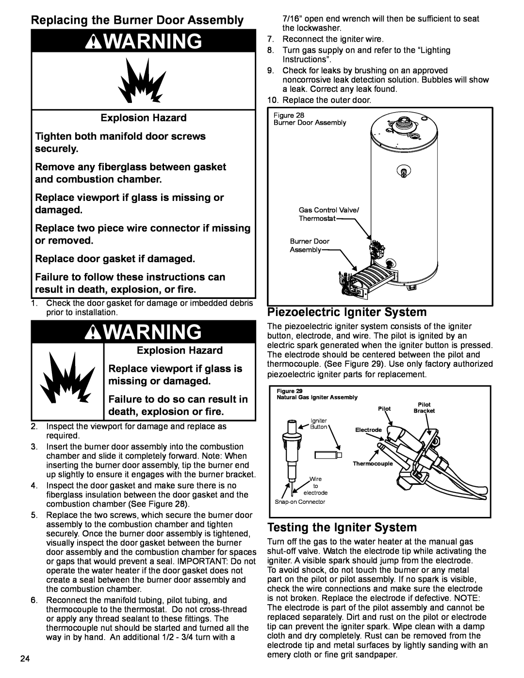
Figure 28
Burner Door Assembly
Gas Control Valve/
Thermostat
Burner Door
Assembly
Piezoelectric Igniter System
The piezoelectric igniter system consists of the igniter button, electrode, and wire. The pilot is ignited by an electric spark generated when the igniter button is pressed. The electrode should be centered between the pilot and thermocouple. (See Figure 29). Use only factory authorized piezoelectric igniter parts for replacement.
Figure 29 |
|
|
Natural Gas Igniter Assembly | Pilot | |
| Pilot | |
| Bracket | |
|
| |
Igniter |
|
|
Button | Electrode |
|
|
| |
| Thermocouple |
|
Wire |
|
|
to |
|
|
electrode |
|
|
|
| |
Testing the Igniter System
Turn off the gas to the water heater at the manual gas