Appendix B - Connector and Cable Pin Outs | 29 |
Appendix B - Connector and Cable Pin Outs
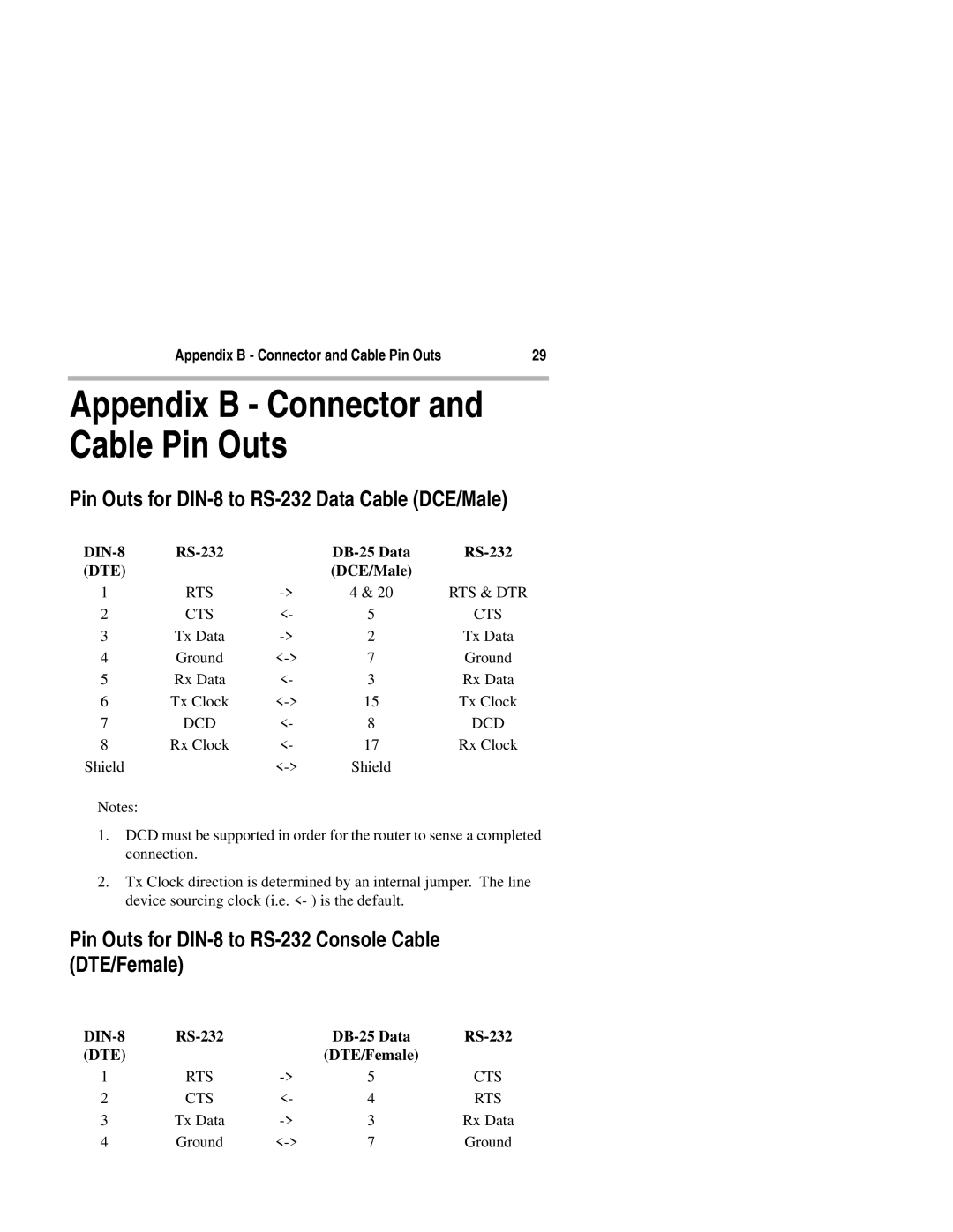
Pin Outs for DIN-8 to RS-232 Data Cable (DCE/Male)
| ||||
(DTE) |
|
| (DCE/Male) |
|
1 | RTS | 4 & 20 | RTS & DTR | |
2 | CTS | <- | 5 | CTS |
3 | Tx Data | 2 | Tx Data | |
4 | Ground | 7 | Ground | |
5 | Rx Data | <- | 3 | Rx Data |
6 | Tx Clock | 15 | Tx Clock | |
7 | DCD | <- | 8 | DCD |
8 | Rx Clock | <- | 17 | Rx Clock |
Shield |
| Shield |
|
Notes:
1.DCD must be supported in order for the router to sense a completed connection.
2.Tx Clock direction is determined by an internal jumper. The line device sourcing clock (i.e. <- ) is the default.
Pin Outs for DIN-8 to RS-232 Console Cable (DTE/Female)
| ||||
(DTE) |
|
| (DTE/Female) |
|
1 | RTS | 5 | CTS | |
2 | CTS | <- | 4 | RTS |
3 | Tx Data | 3 | Rx Data | |
4 | Ground | 7 | Ground |