15G MOTOR & GOVERNOR
| RPM | Part No. |
| 865663 |
|
| 9000 | 867082 |
| 867388 |
|
842970 | 12000 | 867083 |
| 865686 |
|
8656994 |
|
|
| ||
| 14000 | 867084 | 847095 | 864821 |
|
| 18000 | 867085 |
|
| 865687 |
|
|
|
| ||
|
|
|
|
| These parts |
| 867086 |
|
| 864821 are included | |
|
| 864232 | 865663 | in governor | |
| 864234 |
|
| subassembly | |
|
|
| 867388 | ||
|
|
|
|
| |
|
| 865657 | 865693 |
| 812164 |
865655 |
|
|
|
|
|
|
|
|
|
|
|
| 865660 | ||
865695 | 864735 |
| |||||
|
|
|
|
| 865697 |
| |
865787 2 1/2"
865786 3"
865988 4"
865658
865659 | 2 1/2", 3" |
|
|
865991 | 4" |
|
|
844280
864236
865661
|
|
|
865653 | 2 1/2", 3" | |
|
|
|
865990 | 4" | |
|
|
|
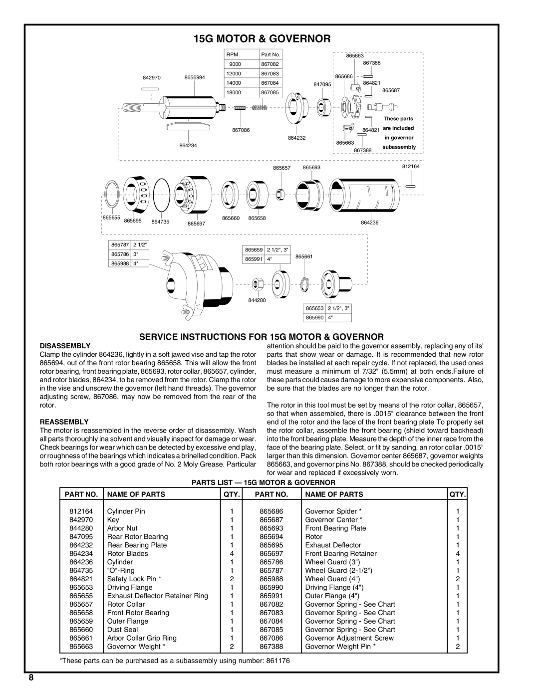
SERVICE INSTRUCTIONS FOR 15G MOTOR & GOVERNOR
DISASSEMBLY
Clamp the cylinder 864236, lightly in a soft jawed vise and tap the rotor 865694, out of the front rotor bearing 865658. This will allow the front rotor bearing, front bearing plate, 865693, rotor collar, 865657, cylinder, and rotor blades, 864234, to be removed from the rotor. Clamp the rotor in the vise and unscrew the governor (left hand threads). The governor adjusting screw, 867086, may now be removed from the rear of the rotor.
REASSEMBLY
The motor is reassembled in the reverse order of disassembly. Wash all parts thoroughly ina solvent and visually inspect for damage or wear. Check bearings for wear which can be detected by excessive end play, or roughness of the bearings which indicates a brinelled condition. Pack both rotor bearings with a good grade of No. 2 Moly Grease. Particular
attention should be paid to the governor assembly, replacing any of its' parts that show wear or damage. It is recommended that new rotor blades be installed at each repair cycle. If not replaced, the used ones must measure a minimum of 7/32" (5.5mm) at both ends.Failure of these parts could cause damage to more expensive components. Also, be sure that the blades are no longer than the rotor.
The rotor in this tool must be set by means of the rotor collar, 865657, so that when assembled, there is .0015" clearance between the front end of the rotor and the face of the front bearing plate To properly set the rotor collar, assemble the front bearing (shield toward backhead) into the front bearing plate. Measure the depth of the inner race from the face of the bearing plate. Select, or fit by sanding, an rotor collar .0015" larger than this dimension. Governor center 865687, governor weights 865663, and governor pins No. 867388, should be checked periodically for wear and replaced if excessively worn.
PARTS LIST — 15G MOTOR & GOVERNOR
PART NO. | NAME OF PARTS | QTY. | PART NO. | NAME OF PARTS | QTY. |
812164 | Cylinder Pin | 1 | 865686 | Governor Spider * | 1 |
842970 | Key | 1 | 865687 | Governor Center * | 1 |
844280 | Arbor Nut | 1 | 865693 | Front Bearing Plate | 1 |
847095 | Rear Rotor Bearing | 1 | 865694 | Rotor | 1 |
864232 | Rear Bearing Plate | 1 | 865695 | Exhaust Deflector | 1 |
864234 | Rotor Blades | 4 | 865697 | Front Bearing Retainer | 4 |
864236 | Cylinder | 1 | 865786 | Wheel Guard (3") | 1 |
864735 | 1 | 865787 | Wheel Guard | 1 | |
864821 | Safety Lock Pin * | 2 | 865988 | Wheel Guard (4") | 2 |
865653 | Driving Flange | 1 | 865990 | Driving Flange (4") | 1 |
865655 | Exhaust Deflector Retainer Ring | 1 | 865991 | Outer Flange (4") | 1 |
865657 | Rotor Collar | 1 | 867082 | Governor Spring - See Chart | 1 |
865658 | Front Rotor Bearing | 1 | 867083 | Governor Spring - See Chart | 1 |
865659 | Outer Flange | 1 | 867084 | Governor Spring - See Chart | 1 |
865660 | Dust Seal | 1 | 867085 | Governor Spring - See Chart | 1 |
865661 | Arbor Collar Grip Ring | 1 | 867086 | Governor Adjustment Screw | 1 |
865663 | Governor Weight * | 2 | 867388 | Governor Weight Pin * | 2 |
|
|
|
|
|
|
*These parts can be purchased as a subassembly using number: 861176
8