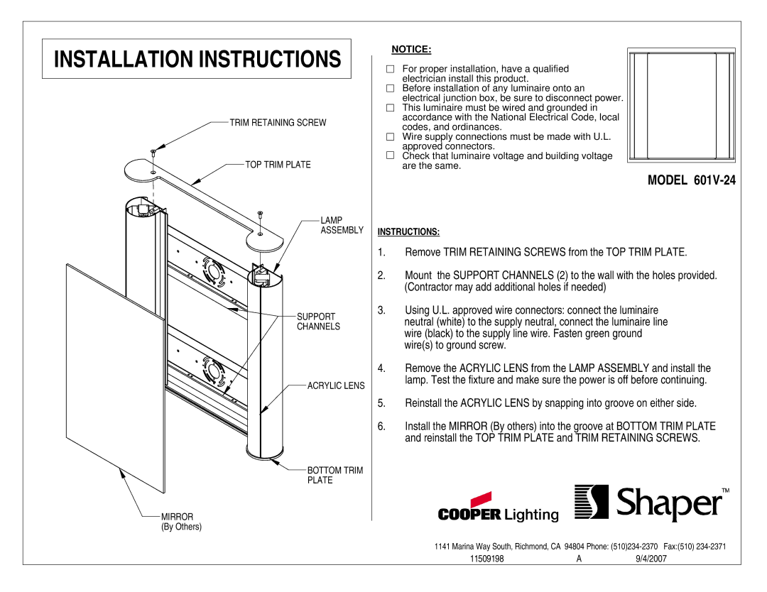
601V-24 specifications
Cooper Lighting's 601V-24 is an innovative lighting fixture designed to meet the demands of modern spaces while providing efficiency and versatility. Ideal for both commercial and industrial applications, this product showcases several cutting-edge features that enhance illumination quality and energy performance.One of the main features of the 601V-24 is its advanced LED technology. LEDs are known for their long lifespan and low energy consumption compared to traditional lighting options. By harnessing the power of LED, the 601V-24 not only delivers bright, uniform light but also significantly reduces electricity costs, making it an environmentally friendly choice. This eco-conscious design addresses energy-saving initiatives prevalent in today's market, aligning with the goal of reducing carbon footprints.
The fixture is equipped with an adjustable lumen output, allowing users to tailor the brightness to their specific needs. This flexibility is particularly beneficial in settings where lighting requirements vary throughout the day or depend on the activities being performed. Whether it's a warehouse needing direct, high-intensity light or a retail space seeking a more ambient atmosphere, the 601V-24 adapts seamlessly.
Another standout characteristic of the 601V-24 is its robust construction. Built to withstand harsh conditions, it features a durable housing designed for easy installation and maintenance. The unit is also rated for wet locations, making it suitable for both indoor and outdoor applications. This durability ensures longevity and reliability, serving users in various environments.
The 601V-24 also incorporates intelligent control technologies, such as motion sensors and dimming capabilities. These enhancements contribute to energy savings by ensuring that lights are only active when necessary, further optimizing power usage. Such smart features are particularly useful in larger facilities where managing energy consumption can lead to substantial savings.
Overall, Cooper Lighting's 601V-24 is a versatile, efficient, and durable lighting solution that meets contemporary lighting demands. Its combination of LED technology, adjustable lighting output, robust construction, and intelligent controls make it a top choice for sustainable and adaptable lighting in both commercial and industrial settings. By opting for this fixture, users invest in not only superior lighting functionality but also in a product that promotes energy efficiency and environmental responsibility.