AV M V I S I O N A R E A
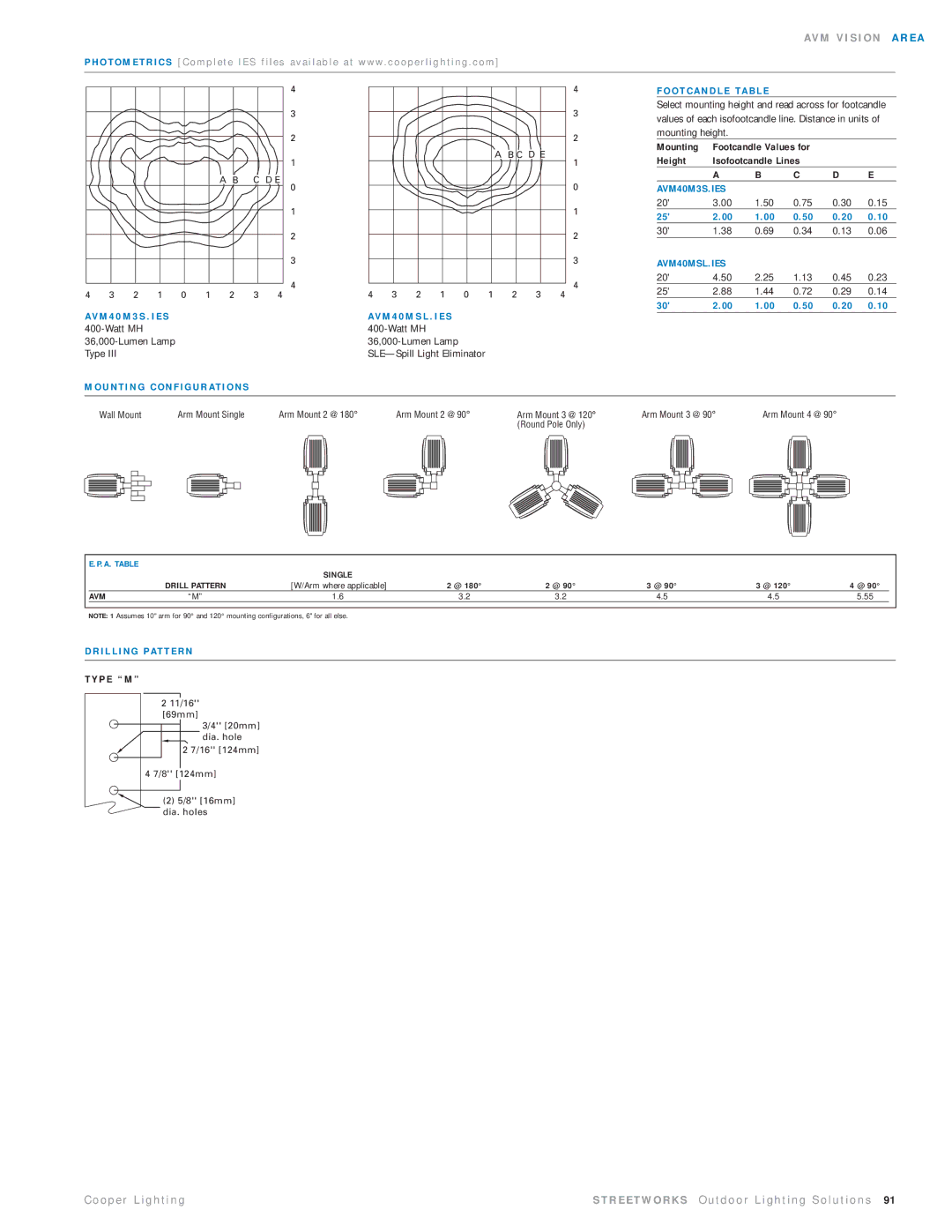
P H O T O M E T R I C S [ C o m p l e t e I E S f i l e s a v a i l a b l e a t w w w . c o o p e r l i g h t i n g . c o m ]
A B C D E
4 3 2 1 0 1 2 3 4
AV M 4 0 M 3 S . I E S 400-Watt MH
Type III
4
3
2
1
0
1
2
3
4
|
|
|
|
|
|
|
| 4 |
|
|
|
|
|
|
|
| 3 |
|
|
|
|
|
|
|
| 2 |
|
|
|
|
|
| A B C D E | 1 | |
|
|
|
|
|
|
|
| |
|
|
|
|
|
|
|
| 0 |
|
|
|
|
|
|
|
| 1 |
|
|
|
|
|
|
|
| 2 |
|
|
|
|
|
|
|
| 3 |
|
|
|
|
|
|
|
| 4 |
4 | 3 | 2 | 1 | 0 | 1 | 2 | 3 | 4 |
AV M 4 0 M S L . I E S |
|
|
|
|
| |||
|
|
|
|
|
| |||
|
|
|
|
| ||||
|
|
|
| |||||
F O O T C A N D L E TA B L E
Select mounting height and read across for footcandle values of each isofootcandle line. Distance in units of mounting height.
Mounting | Footcandle Values for |
|
| ||
Height | Isofootcandle Lines |
|
| ||
| A | B | C | D | E |
AVM40M3S.IES |
|
|
|
| |
20' | 3.00 | 1.50 | 0.75 | 0.30 | 0.15 |
25' | 2.00 | 1.00 | 0.50 | 0.20 | 0.10 |
30' | 1.38 | 0.69 | 0.34 | 0.13 | 0.06 |
AVM40MSL.IES |
|
|
|
| |
20' | 4.50 | 2.25 | 1.13 | 0.45 | 0.23 |
25' | 2.88 | 1.44 | 0.72 | 0.29 | 0.14 |
30' | 2.00 | 1.00 | 0.50 | 0.20 | 0.10 |
M O U N T I N G C O N F I G U R AT I O N S
Wall Mount |
|
|
| Arm Mount Single | Arm Mount 2 @ 180° | Arm Mount 2 @ 90° | Arm Mount 3 @ 120° | Arm Mount 3 @ 90° | Arm Mount 4 @ 90° | ||||||||||||||||||||||
|
|
|
|
|
|
|
|
|
|
|
|
|
|
|
|
|
|
| (Round Pole Only) |
|
|
|
|
|
|
|
|
|
| ||
|
|
|
|
|
|
|
|
|
|
|
|
|
|
|
|
|
|
|
|
|
|
|
|
|
|
|
|
|
|
|
|
| E.P.A. TABLE |
| SINGLE |
|
|
|
|
|
| |
|
|
|
|
|
|
|
|
|
| |
|
|
| DRILL PATTERN | [W/Arm where applicable] | 2 @ 180° | 2 @ 90° | 3 @ 90° | 3 @ 120° | 4 @ 90° |
|
|
| AVM | “M” | 1.6 | 3.2 | 3.2 | 4.5 | 4.5 | 5.55 |
|
|
|
|
|
|
|
|
|
|
|
|
NOTE: 1 Assumes 10" arm for 90° and 120° mounting configurations, 6" for all else.
D R I L L I N G PAT T E R N
T Y P E “ M ”
211/16''
[69mm]
3/4'' [20mm] dia. hole
2 7/16'' [124mm]
4 7/8'' [124mm]
![]() (2) 5/8'' [16mm] dia. holes
(2) 5/8'' [16mm] dia. holes
C o o p e r L i g h t i n g | S T R E E T W O R K S O u t d o o r L i g h t i n g S o l u t i o n s 91 |