INSTALLATION INSTRUCTIONS
IMPORTANT: READ CAREFULLY BEFORE INSTALLING FIXTURE.
Talon Medium
Sheet 1 of 3
11/29/07IMI-687
WARNING: Risk of Fire/Electric Shock. If not qualified, consult an electrician.
WARNING: Risk of Electric Shock. Disconnect power at fuse or circuit breaker before installing or servicing.
WARNING: Risk of Burn. Disconnect power and allow fixture to cool before changing bulb or handling fixture.
WARNING: Risk of Personal Injury. Fixture may become damaged and/or unstable if not installed properly. Tighten all fixture components to their recommended torque values.
WARNING: Risk of Fire/Electrical Shock. Upside down installation can result in overheating or accumulation of water in fixture. Install right side up.
Tools Required Socket, 5/16" Socket, 3/4" Deep Well Socket, Electrical wiring tools.
NOTE: These luminaires are designed for outdoor lighting services, and should not be used in area of limited ventilation or in high ambient temperature enclosures. Construction is suitable for down lighting only. Best results will be obtained if installed and maintained according to the following recommendations.
1.Remove housing assembly and arm components from carton. Remove power tray if fixture is not hard mount version.
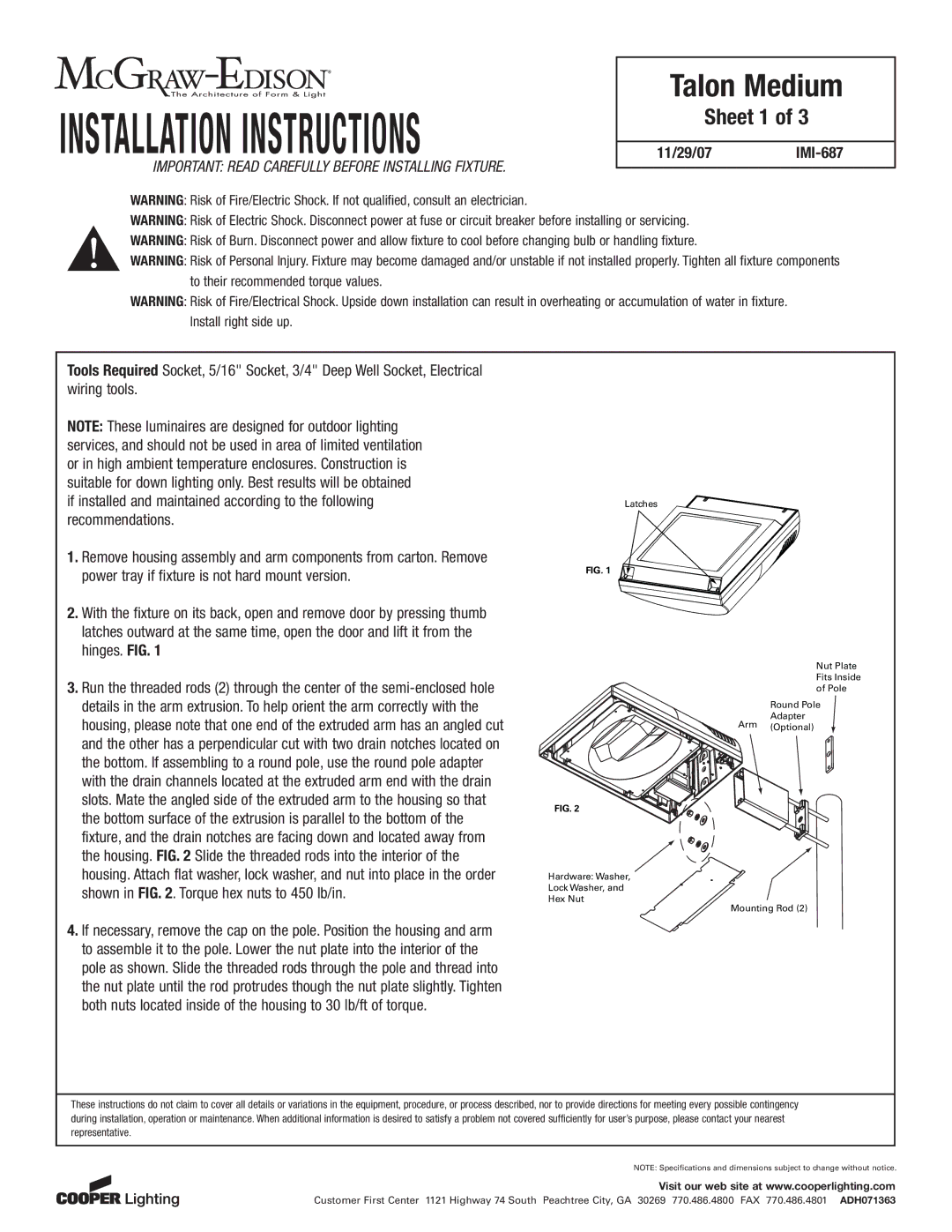
2.With the fixture on its back, open and remove door by pressing thumb latches outward at the same time, open the door and lift it from the hinges. FIG. 1
3.Run the threaded rods (2) through the center of the
Latches
FIG. 1
Nut Plate
Fits Inside
of Pole
Round Pole
Adapter
Arm (Optional)
FIG. 2
Hardware: Washer,
Lock Washer, and
Hex Nut
Mounting Rod (2)
4.If necessary, remove the cap on the pole. Position the housing and arm to assemble it to the pole. Lower the nut plate into the interior of the pole as shown. Slide the threaded rods through the pole and thread into the nut plate until the rod protrudes though the nut plate slightly. Tighten both nuts located inside of the housing to 30 lb/ft of torque.
These instructions do not claim to cover all details or variations in the equipment, procedure, or process described, nor to provide directions for meeting every possible contingency during installation, operation or maintenance. When additional information is desired to satisfy a problem not covered sufficiently for user’s purpose, please contact your nearest representative.
NOTE: Specifications and dimensions subject to change without notice.
Visit our web site at www.cooperlighting.com
Customer First Center 1121 Highway 74 South Peachtree City, GA 30269 770.486.4800 FAX 770.486.4801 ADH071363