INSTALLATION INSTRUCTIONS
IMPORTANT : READ CAREFULLY BEFORE INSTALLING FIXTURE. RETAIN FOR FUTURE REFERENCE
EPL/WM Envoy
Wall Mount Arm
Sheet 1 of 1
4/7/08IMI-695B
GENERAL: Upon receipt of luminaire thoroughly inspect for any freight damage, which should be brought to the attention of the delivery carrier. Compare the catalog description listed on the packing slip with the luminaire label on the housing to assure you have received the correct merchandise.
SAFETY: This luminaire must be wired in accordance with the national electrical code and applicable codes and ordinance. Proper grounding is required to insure personal safety. Carefully observe grounding procedure. All work should be done by a qualified electrician.
WARNING: Make certain power is OFF before starting installation or attempting any maintenance.
WARNING: Risk of Electric Shock. Disconnect power at fuse or circuit breaker before installing or servicing.
WARNING: Risk of Burn. Disconnect power and allow luminaire to cool before changing lamp or handling luminaire.
WARNING: This luminaire is for use with downlight application only.
WARNING: RISK OF FIRE! DO NOT mount on or near combustible materials.
FAILURE TO FOLLOW INSTRUCTIONS MAY RESULT IN SERIOUS INJURY OR DEATH
NOTE: Use minimum 90°C supply wire rating for connections.
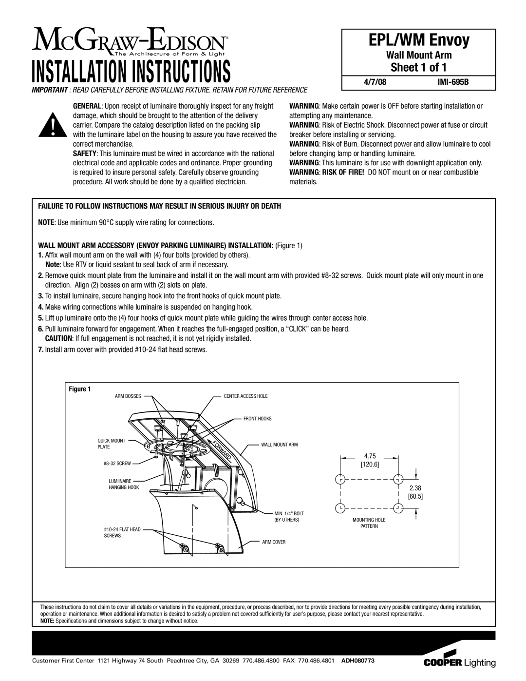
WALL MOUNT ARM ACCESSORY (ENVOY PARKING LUMINAIRE) INSTALLATION: (Figure 1)
1.Affix wall mount arm on the wall with (4) four bolts (provided by others). Note: Use RTV or liquid sealant to seal back of arm if necessary.
2.Remove quick mount plate from the luminaire and install it on the wall mount arm with provided
3.To install luminaire, secure hanging hook into the front hooks of quick mount plate.
4.Make wiring connections while luminaire is suspended on hanging hook.
5.Lift up luminaire onto the (4) four hooks of quick mount plate while guiding the wires through center access hole.
6.Pull luminaire forward for engagement. When it reaches the
7.Install arm cover with provided #10-24 flat head screws.
Figure 1
ARM BOSSES | CENTER ACCESS HOLE | |
| FRONT HOOKS | |
QUICK MOUNT | WALL MOUNT ARM | |
PLATE | ||
|
![]()
LUMIINAIRE ![]()
HANGING HOOK
MIN. 1/4” BOLT (BY OTHERS)
![]() ARM COVER
ARM COVER
4.75
[120.6]
2.38
[60.5]
MOUNTING HOLE
PATTERN
These instructions do not claim to cover all details or variations in the equipment, procedure, or process described, nor to provide directions for meeting every possible contingency during installation, operation or maintenance. When additional information is desired to satisfy a problem not covered sufficiently for user’s purpose, please contact your nearest representative.
NOTE: Specifications and dimensions subject to change without notice.
Customer First Center 1121 Highway 74 South Peachtree City, GA 30269 770.486.4800 FAX 770.486.4801 ADH080773