INSTALLATION INSTRUCTIONS
IMPORTANT : READ CAREFULLY BEFORE INSTALLING FIXTURE. RETAIN FOR FUTURE REFERENCE
Impact Wall Medium
Door Accessories
Sheet 1 of 1
7/22/08IMI-698
GENERAL: Upon receipt of the fixture, thoroughly inspect for any freight damage which should be brought to the attention of the delivery carrier. Compare the catalog description listed on the packing slip with the fixture label on the housing to assure you have received the correct material.
SAFETY: This fixture must be wired in accordance with the National Electrical Code and applicable local codes and ordinances. Proper grounding is required to insure personal safety. Carefully observe grounding procedure under installation section.
WARNING: Risk of Fire/Shock. If not qualified, consult an electrician. Risk of Electric Shock. Disconnect power at fuse or circuit breaker panel or fuse box before installing or servicing.
NOTE: This instruction sheet is applicable for both Trapezoid and Cylinder shapes. Cylinder shape is used for illustration.
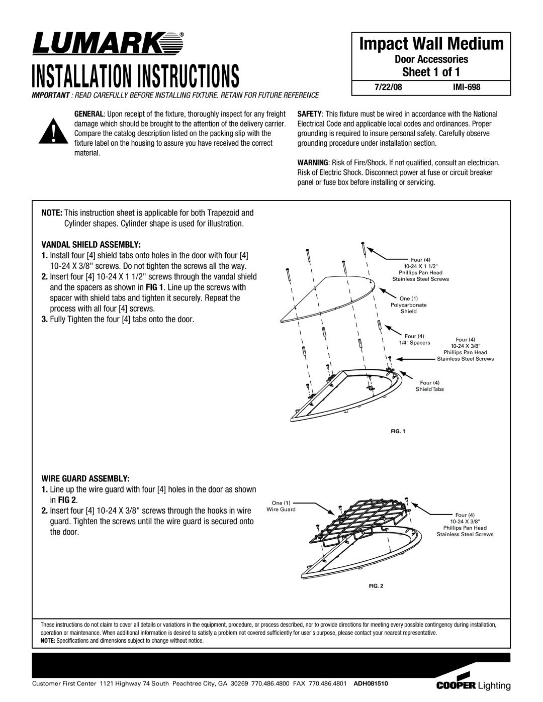
VANDAL SHIELD ASSEMBLY:
1.Install four [4] shield tabs onto holes in the door with four [4]
2.Insert four [4]
3.Fully Tighten the four [4] tabs onto the door.
![]() Four (4)
Four (4)
Phillips Pan Head
Stainless Steel Screws
One (1)
Polycarbonate
Shield
Four (4)
1/4" Spacers Four (4)
Phillips Pan Head
Stainless Steel Screws
Four (4)
ShieldTabs
FIG. 1
WIRE GUARD ASSEMBLY:
1.Line up the wire guard with four [4] holes in the door as shown in FIG 2.
2.Insert four [4]
One (1)
Wire Guard
![]() Four (4)
Four (4)
Phillips Pan Head
Stainless Steel Screws
FIG. 2
These instructions do not claim to cover all details or variations in the equipment, procedure, or process described, nor to provide directions for meeting every possible contingency during installation, operation or maintenance. When additional information is desired to satisfy a problem not covered sufficiently for user’s purpose, please contact your nearest representative.
NOTE: Specifications and dimensions subject to change without notice.
Customer First Center 1121 Highway 74 South Peachtree City, GA 30269 770.486.4800 FAX 770.486.4801 ADH081510