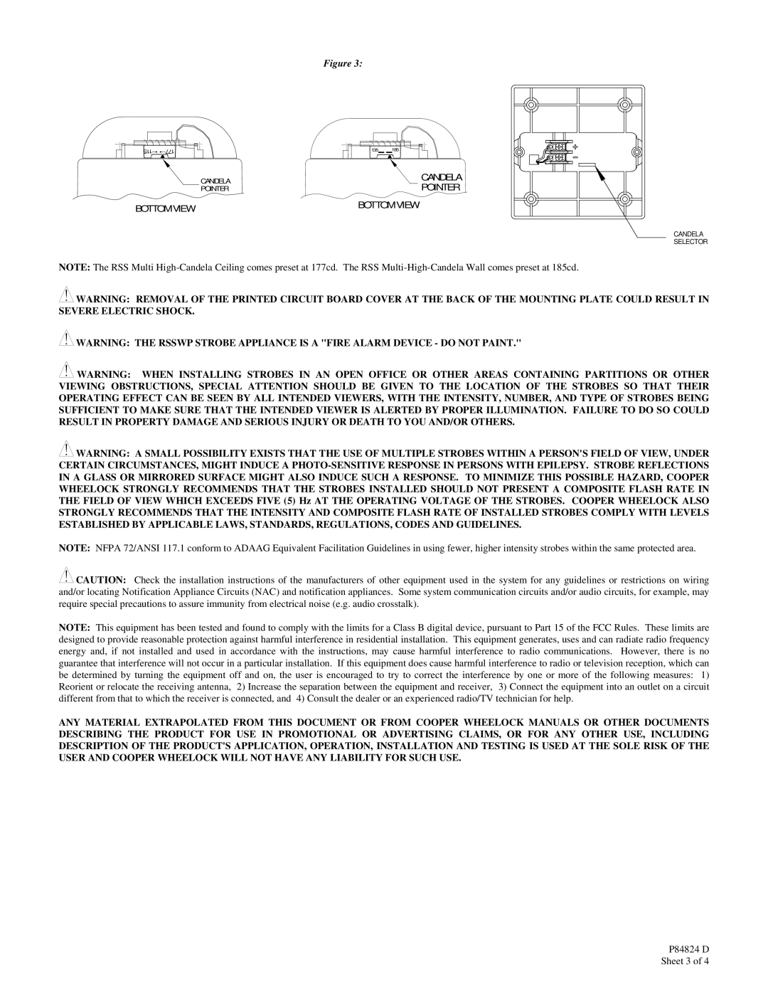
Figure 3:
115 | 177 |
CANDELA
POINTER
BOTTOM VIEW
135 185
CANDELA
POINTER
BOTTOM VIEW
CANDELA
SELECTOR
NOTE: The RSS Multi
![]() WARNING: REMOVAL OF THE PRINTED CIRCUIT BOARD COVER AT THE BACK OF THE MOUNTING PLATE COULD RESULT IN SEVERE ELECTRIC SHOCK.
WARNING: REMOVAL OF THE PRINTED CIRCUIT BOARD COVER AT THE BACK OF THE MOUNTING PLATE COULD RESULT IN SEVERE ELECTRIC SHOCK.
![]() WARNING: THE RSSWP STROBE APPLIANCE IS A "FIRE ALARM DEVICE - DO NOT PAINT."
WARNING: THE RSSWP STROBE APPLIANCE IS A "FIRE ALARM DEVICE - DO NOT PAINT."
![]() WARNING: WHEN INSTALLING STROBES IN AN OPEN OFFICE OR OTHER AREAS CONTAINING PARTITIONS OR OTHER VIEWING OBSTRUCTIONS, SPECIAL ATTENTION SHOULD BE GIVEN TO THE LOCATION OF THE STROBES SO THAT THEIR OPERATING EFFECT CAN BE SEEN BY ALL INTENDED VIEWERS, WITH THE INTENSITY, NUMBER, AND TYPE OF STROBES BEING SUFFICIENT TO MAKE SURE THAT THE INTENDED VIEWER IS ALERTED BY PROPER ILLUMINATION. FAILURE TO DO SO COULD RESULT IN PROPERTY DAMAGE AND SERIOUS INJURY OR DEATH TO YOU AND/OR OTHERS.
WARNING: WHEN INSTALLING STROBES IN AN OPEN OFFICE OR OTHER AREAS CONTAINING PARTITIONS OR OTHER VIEWING OBSTRUCTIONS, SPECIAL ATTENTION SHOULD BE GIVEN TO THE LOCATION OF THE STROBES SO THAT THEIR OPERATING EFFECT CAN BE SEEN BY ALL INTENDED VIEWERS, WITH THE INTENSITY, NUMBER, AND TYPE OF STROBES BEING SUFFICIENT TO MAKE SURE THAT THE INTENDED VIEWER IS ALERTED BY PROPER ILLUMINATION. FAILURE TO DO SO COULD RESULT IN PROPERTY DAMAGE AND SERIOUS INJURY OR DEATH TO YOU AND/OR OTHERS.
![]() WARNING: A SMALL POSSIBILITY EXISTS THAT THE USE OF MULTIPLE STROBES WITHIN A PERSON'S FIELD OF VIEW, UNDER CERTAIN CIRCUMSTANCES, MIGHT INDUCE A
WARNING: A SMALL POSSIBILITY EXISTS THAT THE USE OF MULTIPLE STROBES WITHIN A PERSON'S FIELD OF VIEW, UNDER CERTAIN CIRCUMSTANCES, MIGHT INDUCE A
NOTE: NFPA 72/ANSI 117.1 conform to ADAAG Equivalent Facilitation Guidelines in using fewer, higher intensity strobes within the same protected area.
![]() CAUTION: Check the installation instructions of the manufacturers of other equipment used in the system for any guidelines or restrictions on wiring and/or locating Notification Appliance Circuits (NAC) and notification appliances. Some system communication circuits and/or audio circuits, for example, may require special precautions to assure immunity from electrical noise (e.g. audio crosstalk).
CAUTION: Check the installation instructions of the manufacturers of other equipment used in the system for any guidelines or restrictions on wiring and/or locating Notification Appliance Circuits (NAC) and notification appliances. Some system communication circuits and/or audio circuits, for example, may require special precautions to assure immunity from electrical noise (e.g. audio crosstalk).
NOTE: This equipment has been tested and found to comply with the limits for a Class B digital device, pursuant to Part 15 of the FCC Rules. These limits are designed to provide reasonable protection against harmful interference in residential installation. This equipment generates, uses and can radiate radio frequency energy and, if not installed and used in accordance with the instructions, may cause harmful interference to radio communications. However, there is no guarantee that interference will not occur in a particular installation. If this equipment does cause harmful interference to radio or television reception, which can be determined by turning the equipment off and on, the user is encouraged to try to correct the interference by one or more of the following measures: 1) Reorient or relocate the receiving antenna, 2) Increase the separation between the equipment and receiver, 3) Connect the equipment into an outlet on a circuit different from that to which the receiver is connected, and 4) Consult the dealer or an experienced radio/TV technician for help.
ANY MATERIAL EXTRAPOLATED FROM THIS DOCUMENT OR FROM COOPER WHEELOCK MANUALS OR OTHER DOCUMENTS DESCRIBING THE PRODUCT FOR USE IN PROMOTIONAL OR ADVERTISING CLAIMS, OR FOR ANY OTHER USE, INCLUDING DESCRIPTION OF THE PRODUCT'S APPLICATION, OPERATION, INSTALLATION AND TESTING IS USED AT THE SOLE RISK OF THE USER AND COOPER WHEELOCK WILL NOT HAVE ANY LIABILITY FOR SUCH USE.
