INSTALLATION INSTRUCTIONS

IMPORTANT: READ CAREFULLY BEFORE INSTALLING FIXTURE.

Talon Medium

Sheet 2 of 3

7/23/08IMI-687SW

WARNING: Risk of Fire/Electric Shock. If not qualified, consult an electrician.

WARNING: Risk of Electric Shock. Disconnect power at fuse or circuit breaker before installing or servicing.

WARNING: Risk of Burn. Disconnect power and allow fixture to cool before changing bulb or handling fixture.

WARNING: Risk of Personal Injury. Fixture may become damaged and/or unstable if not installed properly. Tighten all fixture components to their recommended torque values.

WARNING: Risk of Fire/Electrical Shock. Upside down installation can result in overheating or accumulation of water in fixture. Install right side up.

5.With the pole and fixture(s) raised into position, place the power tray onto the hinges of the housing electrical compartment and let

it hang free. Locate the power connector plug and rotate the power tray until the connection can be made with the mating connector in the housing. Raise the powertray until the two wing screws engage and tighten until fully snug.

6.Replace door on the hinges at the rear of the housing, rotate into position, and assure that both latches are fastened securely.

FIXTURE MAINTENANCE

RELAMPING

1.Disengage both latches and open the door. Do not let the door swing freely on the hinges.

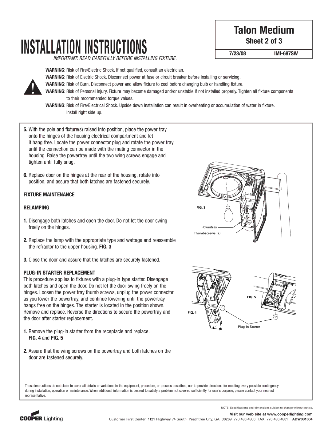
2.Replace the lamp with the appropriate type and wattage and reassemble the refractor to the upper housing. FIG. 3

3.Close the door and assure that the latches are securely fastened.

PLUG-IN STARTER REPLACEMENT

This procedure applies to fixtures with a plug-in type starter. Disengage both latches and open the door. Do not let the door swing freely on the hinges. Loosen the power tray thumb screws, unplug the power connector as you lower the powertray, and continue lowering until the powertray hangs free on the hinges. The starter is located in the position shown. Remove and replace. Reverse the directions to secure the powertray and the door after starter replacement.

1.Remove the plug-in starter from the receptacle and replace. FIG. 4 and FIG. 5

2.Assure that the wing screws on the powertray and both latches on the door are fastened securely.

FIG. 3

Powertray

Thumbscrews (2)

FIG. 5

FIG. 4

Plug-In Starter

These instructions do not claim to cover all details or variations in the equipment, procedure, or process described, nor to provide directions for meeting every possible contingency during installation, operation or maintenance. When additional information is desired to satisfy a problem not covered sufficiently for user’s purpose, please contact your nearest representative.

NOTE: Specifications and dimensions subject to change without notice.

Visit our web site at www.cooperlighting.com

Customer First Center 1121 Highway 74 South Peachtree City, GA 30269 770.486.4800 FAX 770.486.4801 ADW081604

Page 2
Image 2
Cooper Lighting TMU/TLU installation instructions Sheet 2, Fixture Maintenance Relamping, PLUG-IN Starter Replacement

TMU/TLU specifications

Cooper Lighting's TMU/TLU series represents a significant advancement in the realm of commercial and industrial lighting solutions. Designed to meet the demands of modern facilities, these fixtures combine efficiency, durability, and versatility, making them ideal for a variety of applications, including warehouses, distribution centers, and manufacturing environments.

One of the standout features of the TMU/TLU series is its robust construction. Built with high-quality materials, these fixtures are engineered to withstand the rigors of challenging environments. The housings are crafted from die-cast aluminum, offering exceptional strength and resistance to mechanical stress, while also ensuring effective thermal management. This construction enhances the longevity of the lighting solution, reducing the need for frequent replacements and minimizing maintenance costs.

Another key characteristic of the TMU/TLU series is its advanced LED technology. Leveraging the latest in solid-state illumination, these fixtures provide superior energy efficiency compared to traditional lighting options, such as fluorescent or halogen. The use of LED technology significantly reduces energy consumption and lowers operational costs, making it an eco-friendly choice for businesses looking to reduce their carbon footprint.

The TMU/TLU series also offers flexible mounting options to accommodate various installation needs. Whether it's a high-bay or low-bay application, these fixtures can be mounted in multiple orientations, ensuring optimal light distribution throughout the space. This flexibility enables facility managers to customize their lighting layouts based on specific operational requirements.

Furthermore, the TMU/TLU series features advanced controls and smart lighting capabilities. Options for integrated sensors and daylight harvesting technology enhance the system's efficiency by automatically adjusting brightness based on the presence of natural light and the occupancy of the space. This proactive approach to lighting not only improves the comfort of employees but also contributes to energy savings.

In terms of performance, the TMU/TLU series delivers outstanding lumen output and exceptional color rendering. With a high color rendering index (CRI), these fixtures provide accurate color representation, which is critical in applications where color discrimination is vital. This makes them suitable for detailed tasks, ensuring that employees can perform their jobs safely and effectively.

In summary, Cooper Lighting's TMU/TLU series represents a comprehensive lighting solution that combines durability, energy efficiency, and technological innovation. With its robust construction, advanced LED technology, flexible mounting options, and smart controls, this series addresses the diverse needs of modern commercial and industrial spaces while promoting a sustainable approach to lighting.