Continuous Flow Icemaker Service Manual
REFRIGERATION SYSTEM
Air Temperature
|
|
|
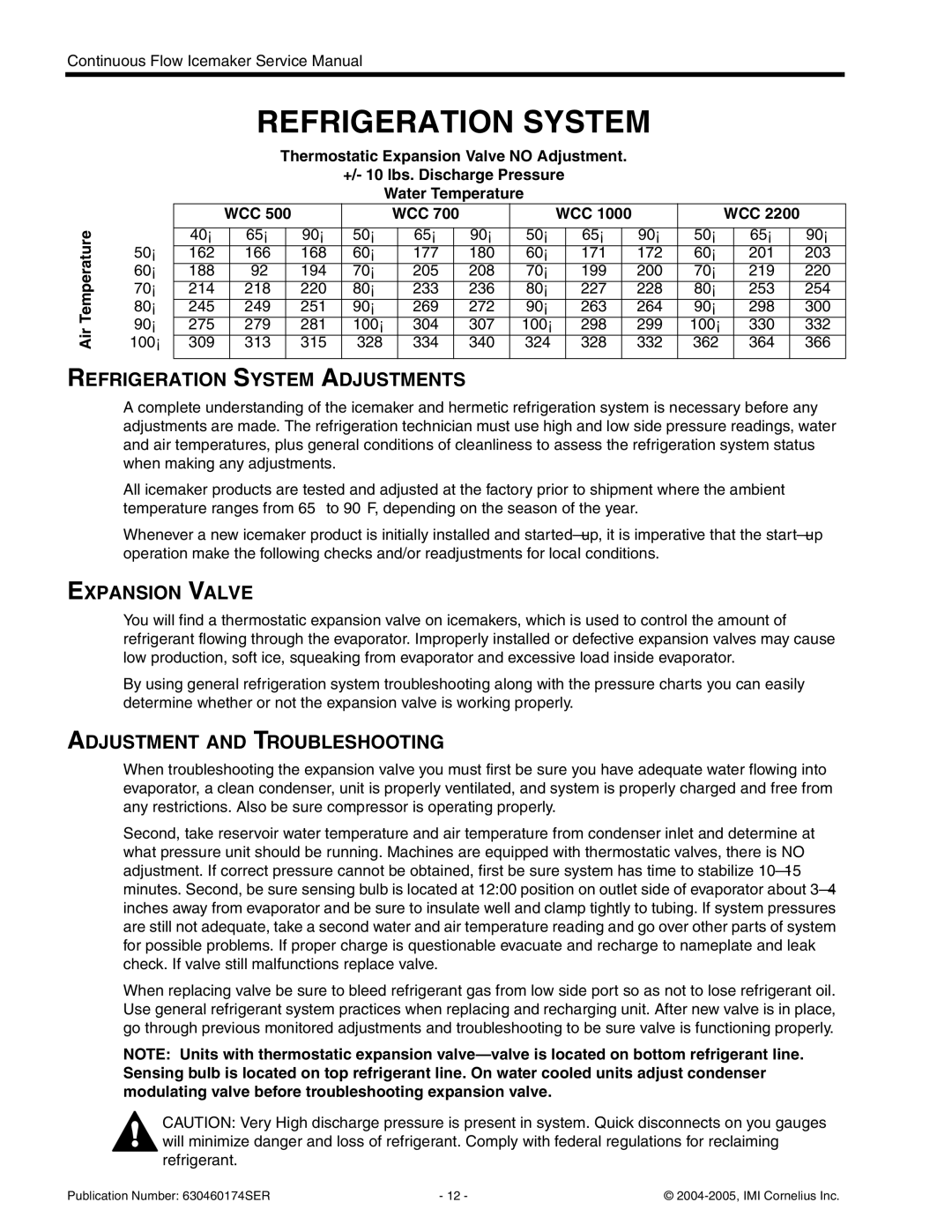
| Thermostatic Expansion Valve NO Adjustment. |
|
|
|
|
|
| ||||||||||
|
|
|
|
|
| +/- 10 lbs. Discharge Pressure |
|
|
|
|
|
| ||||||||
|
|
|
|
|
| Water Temperature |
|
|
|
|
|
|
|
|
| |||||
|
| WCC 500 |
| WCC 700 |
|
| WCC 1000 |
|
| WCC 2200 |
| |||||||||
|
|
|
|
|
|
|
|
|
|
|
|
|
|
|
|
|
|
|
|
|
50° | 40° |
| 65° |
| 90° | 50° |
| 65° |
| 90° | 50° |
| 65° |
| 90° | 50° |
| 65° |
| 90° |
162 |
| 166 |
| 168 | 60° |
| 177 |
| 180 | 60° |
| 171 |
| 172 | 60° |
| 201 |
| 203 | |
60° |
|
|
|
|
|
|
|
|
|
|
|
|
|
|
|
|
|
|
|
|
188 |
| ‘92 |
| 194 | 70° |
| 205 |
| 208 | 70° |
| 199 |
| 200 | 70° |
| 219 |
| 220 | |
70° |
|
|
|
|
|
|
|
|
|
|
|
|
|
|
|
|
|
|
|
|
214 |
| 218 |
| 220 | 80° |
| 233 |
| 236 | 80° |
| 227 |
| 228 | 80° |
| 253 |
| 254 | |
80° |
|
|
|
|
|
|
|
|
|
|
|
|
|
|
|
|
|
|
|
|
245 |
| 249 |
| 251 | 90° |
| 269 |
| 272 | 90° |
| 263 |
| 264 | 90° |
| 298 |
| 300 | |
90° |
|
|
|
|
|
|
|
|
|
|
|
|
|
|
|
|
|
|
|
|
275 |
| 279 |
| 281 | 100° |
| 304 |
| 307 | 100° |
| 298 |
| 299 | 100° |
| 330 |
| 332 | |
100° |
|
|
|
|
|
|
|
|
|
|
|
|
|
|
|
|
|
|
|
|
309 |
| 313 |
| 315 | 328 |
| 334 |
| 340 | 324 |
| 328 |
| 332 | 362 |
| 364 |
| 366 | |
|
|
|
|
|
|
|
|
|
|
|
|
|
|
|
|
|
|
|
|
|
REFRIGERATION SYSTEM ADJUSTMENTS
A complete understanding of the icemaker and hermetic refrigeration system is necessary before any adjustments are made. The refrigeration technician must use high and low side pressure readings, water and air temperatures, plus general conditions of cleanliness to assess the refrigeration system status when making any adjustments.
All icemaker products are tested and adjusted at the factory prior to shipment where the ambient temperature ranges from 65° to 90°F, depending on the season of the year.
Whenever a new icemaker product is initially installed and
EXPANSION VALVE
You will find a thermostatic expansion valve on icemakers, which is used to control the amount of refrigerant flowing through the evaporator. Improperly installed or defective expansion valves may cause low production, soft ice, squeaking from evaporator and excessive load inside evaporator.
By using general refrigeration system troubleshooting along with the pressure charts you can easily determine whether or not the expansion valve is working properly.
ADJUSTMENT AND TROUBLESHOOTING
When troubleshooting the expansion valve you must first be sure you have adequate water flowing into evaporator, a clean condenser, unit is properly ventilated, and system is properly charged and free from any restrictions. Also be sure compressor is operating properly.
Second, take reservoir water temperature and air temperature from condenser inlet and determine at what pressure unit should be running. Machines are equipped with thermostatic valves, there is NO adjustment. If correct pressure cannot be obtained, first be sure system has time to stabilize
When replacing valve be sure to bleed refrigerant gas from low side port so as not to lose refrigerant oil. Use general refrigerant system practices when replacing and recharging unit. After new valve is in place, go through previous monitored adjustments and troubleshooting to be sure valve is functioning properly.
NOTE: Units with thermostatic expansion
CAUTION: Very High discharge pressure is present in system. Quick disconnects on you gauges will minimize danger and loss of refrigerant. Comply with federal regulations for reclaiming refrigerant.
Publication Number: 630460174SER | - 12 - | © |