FOUR CURTAINS
7 CURTAIN SWITCH MUST
BE CONNECTED TO J4,J5,J6, AND J7. SW4–1 OFF
SW4–2 OFF
SW4–3 OFF
March 2, 2004 Rev A 630460064INS

10.To mount bin thermostat in electrical box:

A.Clean the mounting area by rubbing briskly with Scotch Brite pad (see Figure 4 for location).

B.Wipe down the cleaned area with rubbing alcohol and let dry.

C.Pull paper strip off of double sided tape on thermostat mounting bracket.

D.Being sure that bin thermostat is facing the correct direction, (see Figure 4) affix the thermostat in the electrical box. Press firmly down on the mounting bracket to bound the tape.

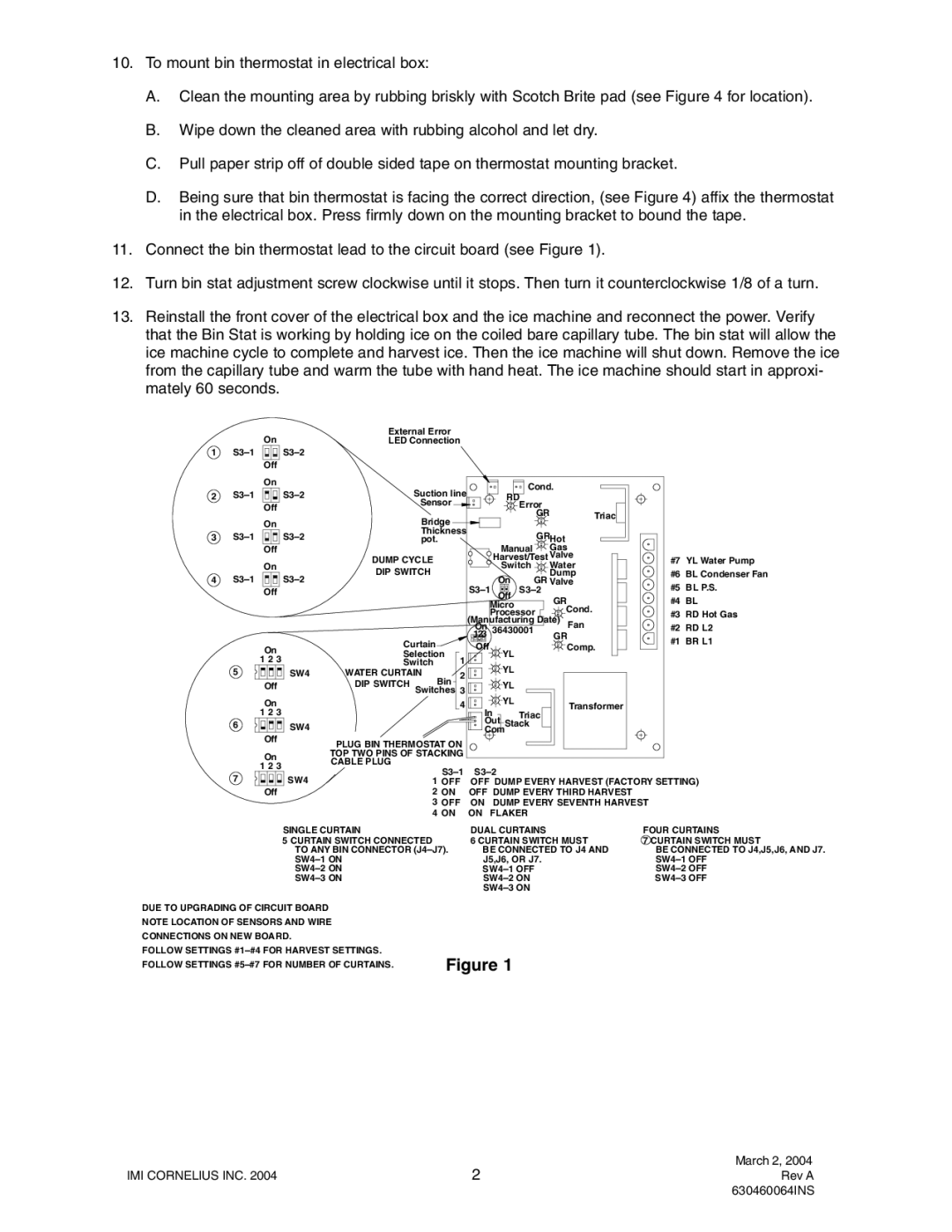
11.Connect the bin thermostat lead to the circuit board (see Figure 1).

12.Turn bin stat adjustment screw clockwise until it stops. Then turn it counterclockwise 1/8 of a turn.

13.Reinstall the front cover of the electrical box and the ice machine and reconnect the power. Verify that the Bin Stat is working by holding ice on the coiled bare capillary tube. The bin stat will allow the ice machine cycle to complete and harvest ice. Then the ice machine will shut down. Remove the ice from the capillary tube and warm the tube with hand heat. The ice machine should start in approxi- mately 60 seconds.

1 S3–1

On

External Error

LED Connection


S3–2


Off


2S3–1

3S3–1

4S3–1

5

6

On

S3–2

Off

On

S3–2

Off

On

S3–2

Off

On 1 2 3

SW4 Off

On 1 2 3

SW4 Off

Suction line

Sensor

Bridge

Thickness pot.

DUMP CYCLE

DIP SWITCH

Curtain


Selection

1

Switch

WATER CURTAIN

2

Bin

DIP SWITCH Switches 3 4

PLUG BIN THERMOSTAT ON TOP TWO PINS OF STACKING

Cond.

RD

Error

GRTriac


GRHot


Manual

Gas


Harvest/Test Valve


Switch

Water


On


Dump


GR Valve

S3–1

Off

S3–2

GR


Micro


Cond.

Processor

(Manufacturing Date)

Fan

On

36430001

GR

123


Off

YL


Comp.


YL


YL


YL


Transformer

In

Triac


Out Stack


Com


#7 YL Water Pump

#6 BL Condenser Fan

#5 BL P.S.

#4 BL

#3 RD Hot Gas #2 RD L2

#1 BR L1

7

On 1 2 3

SW4 Off

CABLE PLUG

S3–1

1 OFF

2 ON

3 OFF

4 ON

S3–2

OFF DUMP EVERY HARVEST (FACTORY SETTING) OFF DUMP EVERY THIRD HARVEST

ON DUMP EVERY SEVENTH HARVEST ON FLAKER

SINGLE CURTAIN

5 CURTAIN SWITCH CONNECTED TO ANY BIN CONNECTOR (J4–J7). SW4–1 ON

SW4–2 ON

SW4–3 ON

DUAL CURTAINS

6 CURTAIN SWITCH MUST BE CONNECTED TO J4 AND J5,J6, OR J7.

SW4–1 OFF

SW4–2 ON

SW4–3 ON

DUE TO UPGRADING OF CIRCUIT BOARD

NOTE LOCATION OF SENSORS AND WIRE CONNECTIONS ON NEW BOARD.

FOLLOW SETTINGS #1–#4 FOR HARVEST SETTINGS. FOLLOW SETTINGS #5–#7 FOR NUMBER OF CURTAINS.

Figure 1

IMI CORNELIUS INC. 2004

2

Page 2
Image 2
Cornelius P/N 630460064, P/N 620037008, P/N 630900413, P/N 630000408, P/N 630000413 installation instructions IMI Cornelius INC

P/N 630000413, P/N 630000408, P/N 630460064, P/N 630900413, P/N 620037008 specifications

Cornelius P/N 620037008, P/N 630900413, P/N 630460064, P/N 630000408, and P/N 630000413 represent a series of innovative components specifically designed for commercial beverage dispensing applications. These specific part numbers indicate specialized attachments and replacement parts that enhance the performance and longevity of beverage dispensing systems while ensuring product consistency and quality.

The Cornelius P/N 620037008 is known for its robust design, ideal for use in high-demand environments. This component focuses on ensuring precise control over beverage flow, crucial for maintaining drinks' carbonization and ensuring customer satisfaction. Its durable materials provide resistance against wear and tear, significantly extending the lifespan of the dispensing mechanism.

P/N 630900413 is engineered with advanced technology to optimize refrigerant flow in beverage dispensing systems. A key feature of this part is its high efficiency, which minimizes energy consumption while ensuring that beverages remain cool and refreshing. This part is also designed to be easily integrated into existing systems, providing an upgrade path without the need for complete system overhauls.

P/N 630460064 offers features aimed at improving the overall user experience. This component enhances the simplicity of sanitation procedures, reducing downtime between product changes. Additionally, its user-friendly design ensures that operators can perform maintenance tasks quickly and efficiently, thus supporting continuous operation in busy settings.

P/N 630000408 and P/N 630000413 are critical in ensuring the optimal mixture and delivery of beverage products, maintaining consistent flavor profiles across different serving conditions. These parts are engineered to accommodate a range of beverage types, from carbonated soft drinks to specialty beverages, making them versatile choices for diverse establishments.

In conclusion, the Cornelius P/N 620037008, P/N 630900413, P/N 630460064, P/N 630000408, and P/N 630000413 represent a suite of components that are essential for maintaining high standards in beverage dispensing. Their main features, advanced technologies, and specific characteristics cater to the unique demands of the beverage industry, ensuring reliable, efficient, and quality service across various applications. These components not only improve operational efficiency but also enhance the customer experience, reaffirming Cornelius's commitment to excellence in beverage solutions.