•Remove the shoulder screws, thrust washers, and bell washers that go through the pivot arms to the front support brace. The front support brace and lock nut can be removed at this time as well.
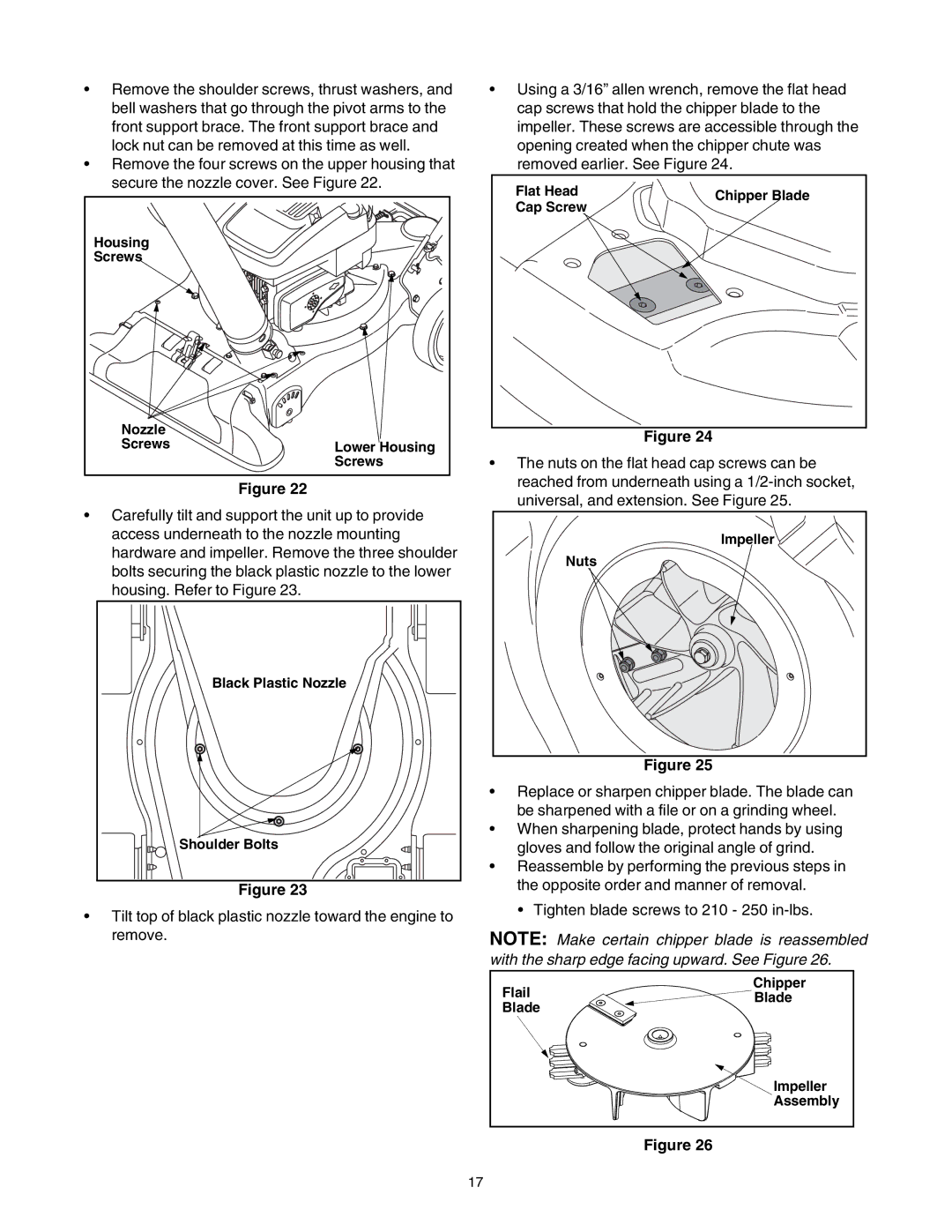
•Remove the four screws on the upper housing that secure the nozzle cover. See Figure 22.
Housing |
|
Screws |
|
Nozzle |
|
Screws | Lower Housing |
| Screws |
Figure 22
•Carefully tilt and support the unit up to provide access underneath to the nozzle mounting hardware and impeller. Remove the three shoulder bolts securing the black plastic nozzle to the lower housing. Refer to Figure 23.
Black Plastic Nozzle |
Shoulder Bolts |
Figure 23
•Tilt top of black plastic nozzle toward the engine to remove.
•Using a 3/16” allen wrench, remove the flat head cap screws that hold the chipper blade to the impeller. These screws are accessible through the opening created when the chipper chute was removed earlier. See Figure 24.
Flat Head | Chipper Blade | |
Cap Screw | ||
|
Figure 24
•The nuts on the flat head cap screws can be reached from underneath using a
Impeller
Nuts
Figure 25
•Replace or sharpen chipper blade. The blade can be sharpened with a file or on a grinding wheel.
•When sharpening blade, protect hands by using gloves and follow the original angle of grind.
•Reassemble by performing the previous steps in the opposite order and manner of removal.
• Tighten blade screws to 210 - 250
NOTE: Make certain chipper blade is reassembled with the sharp edge facing upward. See Figure 26.
Flail | Chipper | |
Blade | ||
Blade | ||
| ||
| Impeller | |
| Assembly |
Figure 26
17