ATTACHING THE HANDLE
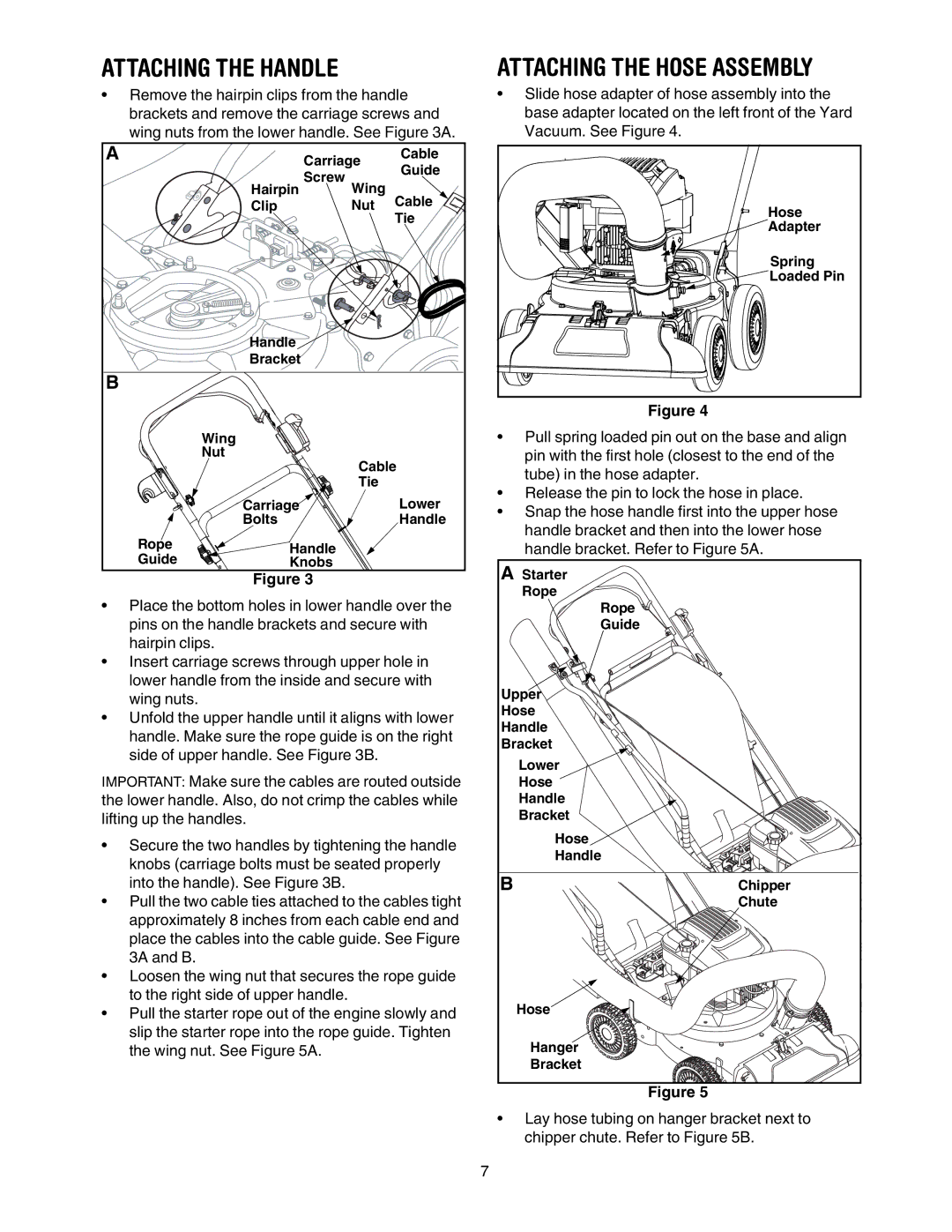
•Remove the hairpin clips from the handle brackets and remove the carriage screws and wing nuts from the lower handle. See Figure 3A.
A | Carriage | Cable | |
| Guide | ||
| Screw |
| |
| Wing |
| |
| Hairpin | Cable | |
| Clip | Nut | |
|
|
| Tie |
| Handle |
|
|
| Bracket |
|
|
B |
|
|
|
| Wing |
|
|
| Nut | Cable | |
|
| ||
|
| Tie |
|
| Carriage |
| Lower |
| Bolts |
| Handle |
Rope | Handle |
|
|
Guide |
|
| |
Knobs |
|
| |
| Figure 3 |
|
|
•Place the bottom holes in lower handle over the pins on the handle brackets and secure with hairpin clips.
•Insert carriage screws through upper hole in lower handle from the inside and secure with wing nuts.
•Unfold the upper handle until it aligns with lower handle. Make sure the rope guide is on the right side of upper handle. See Figure 3B.
IMPORTANT: Make sure the cables are routed outside the lower handle. Also, do not crimp the cables while lifting up the handles.
•Secure the two handles by tightening the handle knobs (carriage bolts must be seated properly into the handle). See Figure 3B.
•Pull the two cable ties attached to the cables tight approximately 8 inches from each cable end and place the cables into the cable guide. See Figure 3A and B.
•Loosen the wing nut that secures the rope guide to the right side of upper handle.
•Pull the starter rope out of the engine slowly and slip the starter rope into the rope guide. Tighten the wing nut. See Figure 5A.
ATTACHING THE HOSE ASSEMBLY
•Slide hose adapter of hose assembly into the base adapter located on the left front of the Yard Vacuum. See Figure 4.
Hose
Adapter
Spring |
Loaded Pin |
Figure 4
•Pull spring loaded pin out on the base and align pin with the first hole (closest to the end of the tube) in the hose adapter.
•Release the pin to lock the hose in place.
•Snap the hose handle first into the upper hose handle bracket and then into the lower hose handle bracket. Refer to Figure 5A.
A Starter |
|
Rope |
|
Rope |
|
Guide |
|
Upper |
|
Hose |
|
Handle |
|
Bracket |
|
Lower |
|
Hose |
|
Handle |
|
Bracket |
|
Hose |
|
Handle |
|
B | Chipper |
| Chute |
Hose |
|
Hanger |
|
Bracket |
|
Figure 5
•Lay hose tubing on hanger bracket next to chipper chute. Refer to Figure 5B.
7