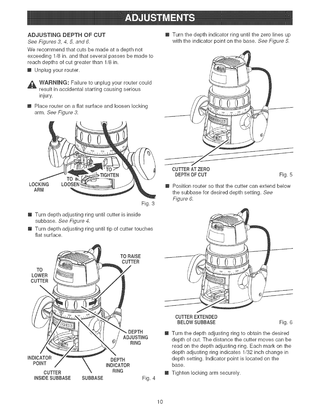
ADJUSTmNGDEPTHOFCUT | [] Turn the | depth indicator | ring until the zero fines up | |||
See Figures 3, 4, 5, and 6. | with the | indicator point | on the base. See F_gure 5. | |||
We recommend that cuts be made at a depth not |
|
| ||||
exceeding 1/8 in. and that several passes be made to |
|
| ||||
reach depths of cut greater than 1/8 in. |
|
|
| |||
[] | Unplug your router. |
|
|
| ||
_ | WARNING: | Failure to unplug your router | could |
|
| |
| result in accidental starting causing serious |
|
|
| ||
[] Place | router on | a fiat surface and loosen locking |
|
| ||
| arm. | See Figure 3. |
|
|
| |
CUTTERAT ZERO |
|
DEPTHOFCUT | Fig. 5 |
LOCKING LOOSEN ARM
[] Position router so that the cutter can extend below the subbase for desired depth setting. See
Figure 6.
Fig. 3
[] Turn depth adjusting ring until cutter is inside subbase. See Figure 4.
[] Turn depth adjusting ring until tip of cutter touches fiat surface.
TO RAISE
CUTTER
TO
LOWER
CUTTER
\
|
|
| CUTTEREXTENDED |
| |
|
|
| BELOWSUBBASE | Fig. 6 | |
| DEPTH | [] Turn the depth adjusting ring to obtain the desired | |||
| ADJUSTING | ||||
| depth of cut. The distance the cutter moves can be | ||||
| RiNG |
| |||
|
| read on the depth adjusting ring. Each mark on the | |||
|
|
| |||
iNDICATOR |
|
| depth adjusting ring indicates 1/32 inch change in | ||
DEPTH |
| depth setting, | indicator point is located | on the | |
POINT |
| ||||
iNDiCATOR |
| base. |
|
| |
|
|
|
| ||
CUTTER | RiNG |
| [] Tighten locking | arm securely. |
|
|
|
| |||
iNSiDESUBBASE | SUBBASE | Fig. 4 |
|
|
|
10
