CARTON CONTENTS
Check carton contents against the fol- lowing list.
Model 358.745340
•Trimmer
•Shield
•Assist handle with wing nut and bolt Examine parts for damage. Do not use damaged parts.
NOTE: If you need assistance or find
parts missing or damaged, call
ASSEMBLY
_.WARNING: If received
assembled, review all assembly steps
to ensure your unit is properly as- sembled and all fasteners are secure.
TUBE ASSEMBLY
Upper Locking Sleeve Assembly
Wires
Lower Locking Sleeve Assembly
1.Align upper tube groove with triangle on lower locking sleeve assembly. Push tubes together un- til they snap into place.
Upper Tube
Groove E_<_
Alignment Triangle
2.Try to pull tubes back apart. If the tubes do not come apart, they are properly snapped into place. If the tubes come apart, repeat step 1 and push until the tubes snap into place.
3.Slide upper locking sleeve assem- bly over lower locking sleeve as-
sembly and tighten by turning clockwise.
A
A_ WARNING: Failure to completely enclose excess wires in upper tube dur- ing assembly of the unit may result in damage to the wires and/or the unit or
serious injury to the operator including electrocution.
AllWARNING: | The upper and low- |
er tubes must remain permanently as- sembled together and the locking sleeve assembly must be fully tight- ened before and during use to avoid serious injury to the operator and/or damage to the unit. DO NOT attempt to disassemble unit after initial assembly.
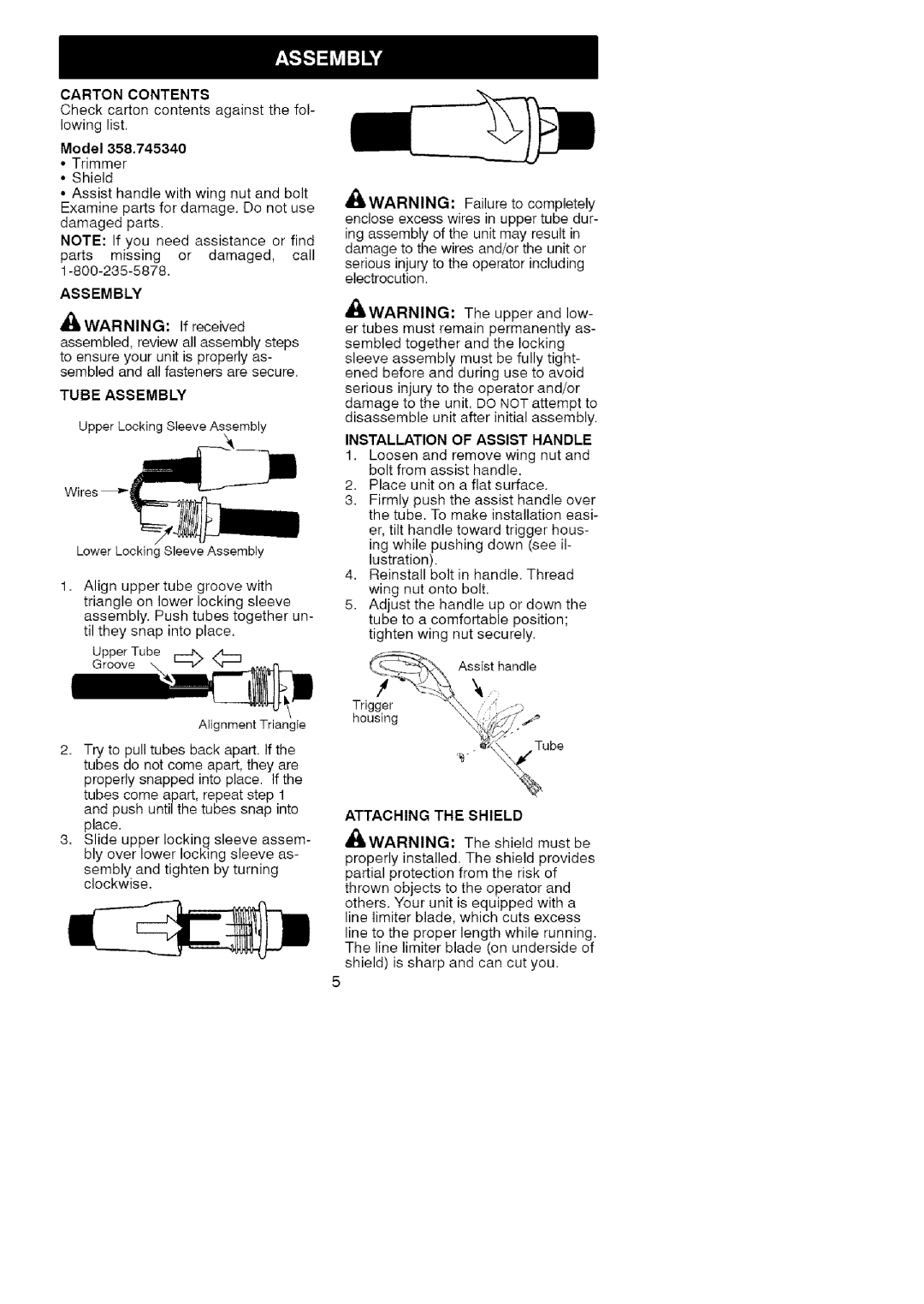
INSTALLATION OF ASSIST HANDLE
1.Loosen and remove wing nut and bolt from assist handle.
2.Place unit on a flat surface.
3.Firmly push the assist handle over the tube. To make installation easi-
er, tilt handle toward trigger hous- ing while pushing down (see il- lustration).
4.Reinstall bolt in handle. Thread wing nut onto bolt.
5.Adjust the handle up or down the tube to a comfortable position; tighten wing nut securely.
_} | As_st | handle |
Trig ge_r | m._ | |
| _ | Tube |
| '_ | \% |
ATTACHING THE SHIELD
_&WARNING: The shield must be
properly installed. The shield provides partial protection from the risk of thrown objects to the operator and others. Your unit is equipped with a line limiter blade, which cuts excess line to the proper length while running. The line limiter blade (on underside of shield) is sharp and can cut you.
5