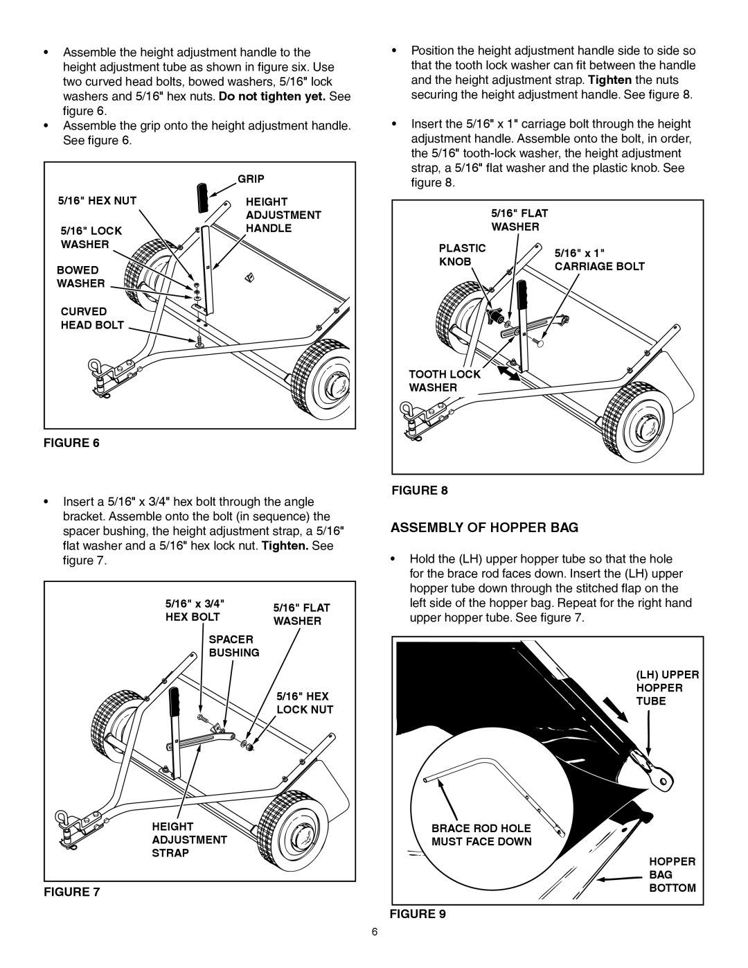
•Assemble the height adjustment handle to the height adjustment tube as shown in fi gure six. Use two curved head bolts, bowed washers, 5/16" lock washers and 5/16" hex nuts. Do not tighten yet. See fi gure 6.
•Assemble the grip onto the height adjustment handle. See fi gure 6.
| GRIP |
5/16" HEX NUT | HEIGHT |
| ADJUSTMENT |
5/16" LOCK | HANDLE |
WASHER |
|
BOWED |
|
WASHER |
|
CURVED |
|
HEAD BOLT |
|
FIGURE 6
•Insert a 5/16" x 3/4" hex bolt through the angle bracket. Assemble onto the bolt (in sequence) the spacer bushing, the height adjustment strap, a 5/16" fl at washer and a 5/16" hex lock nut. Tighten. See
fi gure 7.
5/16" x 3/4" | 5/16" FLAT | |
HEX BOLT | ||
WASHER | ||
|
SPACER
BUSHING
5/16" HEX LOCK NUT
•Position the height adjustment handle side to side so that the tooth lock washer can fi t between the handle and the height adjustment strap. Tighten the nuts securing the height adjustment handle. See fi gure 8.
•Insert the 5/16" x 1" carriage bolt through the height adjustment handle. Assemble onto the bolt, in order, the 5/16"
5/16" FLAT WASHER
PLASTIC | 5/16" x 1" | |
KNOB | ||
CARRIAGE BOLT | ||
|
TOOTH LOCK
WASHER
FIGURE 8
ASSEMBLY OF HOPPER BAG
•Hold the (LH) upper hopper tube so that the hole for the brace rod faces down. Insert the (LH) upper hopper tube down through the stitched fl ap on the left side of the hopper bag. Repeat for the right hand upper hopper tube. See fi gure 7.
(LH) UPPER HOPPER TUBE
HEIGHT | BRACE ROD HOLE |
ADJUSTMENT | MUST FACE DOWN |
STRAP | HOPPER |
| |
| BAG |
FIGURE 7 | BOTTOM |
|
FIGURE 9
6