
CA125D specifications
The Crate Amplifiers CA125D is an innovative hybrid amplifier renowned for delivering superior sound quality and versatility. Musicians and audio professionals alike appreciate this robust amplifier for its powerful performance and user-friendly design, making it a reliable choice for both practice and live performances.One of the standout features of the CA125D is its hybrid design, combining both solid-state and tube circuitry. This unique approach allows the amplifier to deliver the warmth and richness associated with tube amps while also providing the reliability and durability of solid-state technology. The result is a dynamic sound that can adapt to various musical styles and applications.
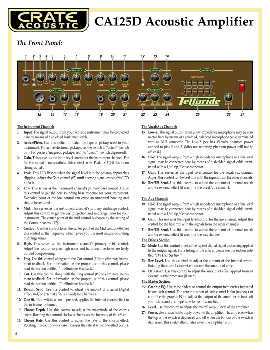
The CA125D comes equipped with a 125-watt RMS power output, capable of driving even the most demanding speakers. This high power rating allows it to be used in larger venues without compromising sound quality or clarity. The amplifier also features dual channels, which enable users to customize their sound by blending clean tones with overdriven sounds. Each channel is equipped with its own set of controls for gain, treble, mid, and bass, allowing for complete tonal shaping.
Another noteworthy technology integrated into the CA125D is the built-in digital effects processor. This processor includes a range of effects such as reverb, delay, chorus, and more, allowing musicians to enhance their sound without the need for external pedals or equipment. The effects can easily be adjusted to suit individual preferences, making it an incredibly versatile tool for creative expression.
The amplifier also features an auxiliary input, which allows musicians to connect external devices such as smartphones or tablets. This capability is perfect for practicing along with tracks or backing music, making the CA125D an excellent choice for both rehearsals and performances.
In terms of connectivity, the CA125D is equipped with a direct output for recording purposes. This output ensures that users can capture their sound accurately, whether for studio recording or live sound reinforcement.
Overall, the Crate Amplifiers CA125D stands out in the market for its combination of power, versatility, and user-centric features. With its hybrid technology, digital effects, and robust connectivity options, it is a top choice for musicians looking to enhance their performance and sound quality.