KX-50 Keyboard Amplifier
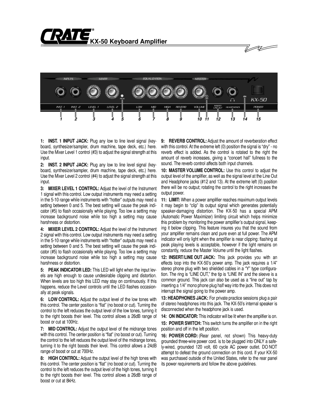
1: INST. 1 INPUT JACK: Plug any low to line level signal (key- | 9: REVERB CONTROL: Adjust the amount of reverberation effect |
board, synthesizer/sampler, drum machine, tape deck, etc.) here. | with this control. At the extreme left (0) position the signal is “dry” - no |
Use the Mixer Level 1 control (#3) to adjust the signal strength at this | reverb effect is added. As the control is rotated to the right the |
input. | amount of reverb increases, giving a “concert hall” fullness to the |
2: INST. 2 INPUT JACK: Plug any low to line level signal (key- | sound. The reverb control affects both input channels. |
board, synthesizer/sampler, drum machine, tape deck, etc.) here. | 10: MASTER VOLUME CONTROL: Use this control to adjust the |
Use the Mixer Level 2 control (#4) to adjust the signal strength at this | output level of the amplifier, as well as the signal level at the Line Out |
input. | and Headphone jacks (#12 and 13). At the extreme left (0) position |
3: MIXER LEVEL 1 CONTROL: Adjust the level of the Instrument | there will be no output; rotating the control to the right increases the |
1 signal with this control. Low output instruments may need a setting | output power. |
in the
setting between 0 and 5. The best setting will cause the peak indi- | it may begin to “clip” its output signal which generates potentially |
cator (#5) to flash occasionally while playing. Too low a setting may | |
increase background noise while too high a setting may cause | (Automatic Power Maximizer) limiting circuit which helps minimize |
harshness or distortion. | this problem by monitoring the power amplifier’s output signal, keep- |
4: MIXER LEVEL 2 CONTROL: Adjust the level of the Instrument | ing it below clipping. This feature insures you that the sound from |
2 signal with this control. Low output instruments may need a setting | your amplifier remains clean and pure even at full power. The APM |
in the | indicator will only light when the amplifier is near clipping: flashing at |
setting between 0 and 5. The best setting will cause the peak indi- | peak playing levels is acceptable, however if the light remains on |
cator (#5) to flash occasionally while playing. Too low a setting may | constantly, reduce the Master Volume until the light flashes. |
increase background noise while too high a setting may cause | 12: INSERT/LINE OUT JACK: This jack provides you with an |
harshness or distortion. | effects loop into the |
5: PEAK INDICATOR LED: This LED will light when the input lev- | stereo phone plug with two shielded cables in a “Y” type configura- |
els are high enough to cause undesirable clipping and distortion. | tion. The ring is “LINE OUT,” the tip is “LINE IN” and the sleeve is a |
When levels are too high this LED may stay on continuously. If this | common ground. This jack can also be used as a “line out” tap by |
happens, reduce the Level controls until the LED flashes occasion- | inserting a 1/4” mono phone plug half way into the jack. This does not |
ally at peak signals. | interrupt the signal going to the power amp. |
6: LOW CONTROL: Adjust the output level of the low tones with | 13: HEADPHONES JACK: For private practice sessions plug a pair |
this control. The center position is “flat” (no boost or cut). Turning the | of stereo headphones into this jack. The |
control to the left reduces the output level of the low tones, turning it | disconnected when the headphone jack is used. |
to the right boosts their level. This control allows a 26dB range of | 14: ON INDICATOR: This indicator will be lit when the amplifier is on. |
boost or cut at 100Hz. | 15: POWER SWITCH: This switch turns the amplifier on in the right |
7: MID CONTROL: Adjust the output level of the midrange tones | position and off in the left position. |
with this control. The center position is “flat” (no boost or cut). Turning | 16: POWER CORD: (Rear panel, not shown) This |
the control to the left reduces the output level of the midrange tones, | grounded |
turning it to the right boosts their level. This control allows a 24dB | |
range of boost or cut at 700Hz. | attempt to defeat the ground connection on this cord. If your |
8: HIGH CONTROL: Adjust the output level of the high tones with | was purchased outside of the United States, refer to the rear panel |
this control. The center position is “flat” (no boost or cut). Turning the | its power requirements and follow the above guidelines. |
control to the left reduces the output level of the high tones, turning it |
|
to the right boosts their level. This control allows a 26dB range of |
|
boost or cut at 8kHz. |
|