INSTALLATION INSTRUCTIONS
TECHNICAL DATA
Gas connection | Rp 1/2 (1/2" BSP female) |
Gas supply | G20 at 20 mbar. |
Pressure test point | Grill injector |
Electrical connection | Flexible cord fitted with a 3 pin 13 amp plug. |
| 230 - 240 a.c. 50HZ 3A fuse |
| NATURAL GAS (G20) | |
|
|
|
Burner | Heat Input | Injector |
|
|
|
Grill | 3.7 kW | 150 |
|
|
|
Oven | 2.5 kW | 110 |
1. GENERAL
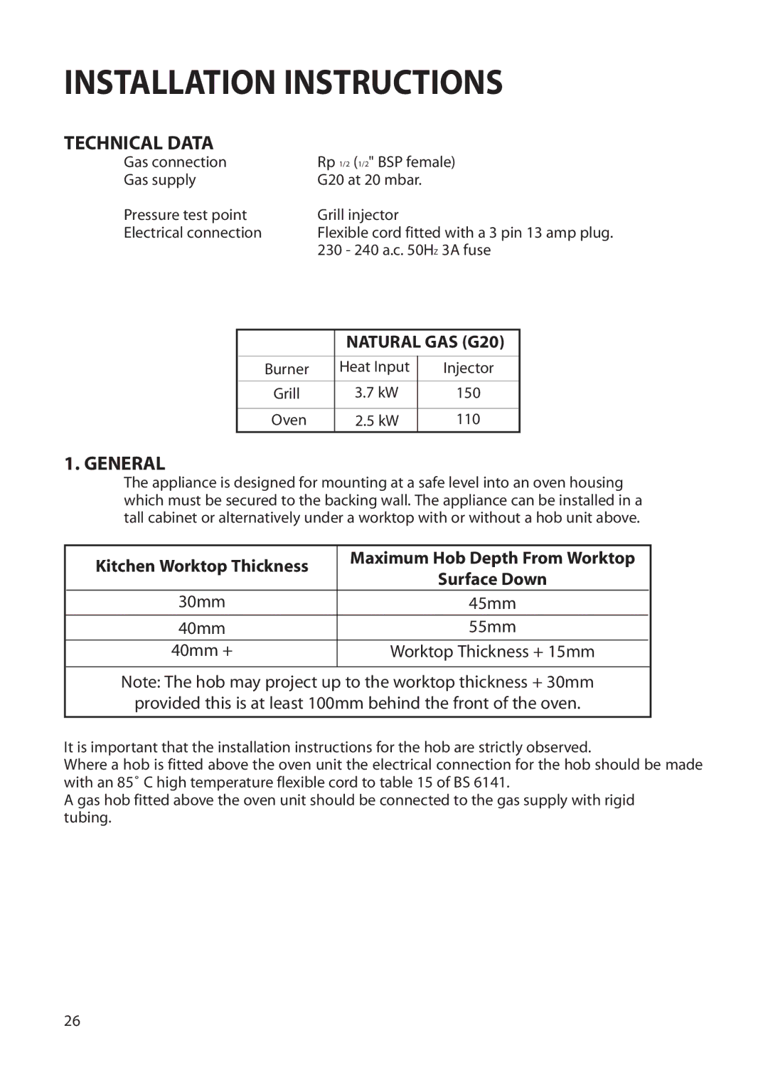
The appliance is designed for mounting at a safe level into an oven housing which must be secured to the backing wall. The appliance can be installed in a tall cabinet or alternatively under a worktop with or without a hob unit above.
| Kitchen Worktop Thickness | Maximum Hob Depth From Worktop |
|
| Surface Down |
| |
|
|
| |
| 30mm | 45mm |
|
| 40mm | 55mm |
|
| 40mm + | Worktop Thickness + 15mm |
|
|
|
|
|
Note: The hob may project up to the worktop thickness + 30mm provided this is at least 100mm behind the front of the oven.
It is important that the installation instructions for the hob are strictly observed.
Where a hob is fitted above the oven unit the electrical connection for the hob should be made with an 85˚ C high temperature flexible cord to table 15 of BS 6141.
A gas hob fitted above the oven unit should be connected to the gas supply with rigid tubing.
26
