@crown® * System® Product Reference
MPX-6™ Mixer-Router
DSPI | ENABLE |
|
|
120 VAC | AUX | CROWN | BUS | AUDIO |
| STACK | AUDIO | STACK | AUDIO | ADD 25 | AUDIO | ADD 25 | AUDIO | ADD 25 | AUDIO | ADD 25 | AUDIO | ADD 25 | AUDIO | ADD 25 | ||||||||||
60 Hz | SERIAL DATA LOOP | OUT |
| IN |
| OUT |
| IN |
| IN | 0 | 5 FOR MIC | IN | 0 | 5 FOR MIC | IN | 0 | 5 FOR MIC | IN | 0 | 5 FOR MIC | IN | 0 | 5 FOR MIC | IN | 0 | 5 FOR MIC | |||
CTRL |
|
|
|
| ||||||||||||||||||||||||||
|
|
|
| 2 MAIN |
|
| 1 MAIN |
|
| 6 | 10 | 5 | 10 | 4 | 10 | 3 | 10 | 2 | 10 | 1 | 10 | |||||||||
|
| IN | OUT | IN |
| BUS |
| BUS | 15 | 15 | 15 | 15 | 15 | 15 | ||||||||||||||||
|
|
| + – | + – |
|
| 21 | 21 | 21 | 21 | 21 | 21 | ||||||||||||||||||
20 W |
| INPUT |
|
|
|
|
|
|
|
|
|
|
|
| M L P |
|
| M L P |
|
| M L P |
|
| M L P |
|
| M L P |
|
| M L P |
|
|
| + | – | + | – | + | – | + | – | + | – |
| + | – |
| + | – |
| + | – |
| + | – |
| + | – |
| ||
| RS232 / RS422 / PA422 | GROUND |
|
|
|
|
|
|
|
| ||||||||||||||||||||
| ONLY |
|
|
|
|
|
|
|
| |||||||||||||||||||||
OVERVIEW
What is an MPX-6?
The
HARDWARE BLOCK DIAGRAM
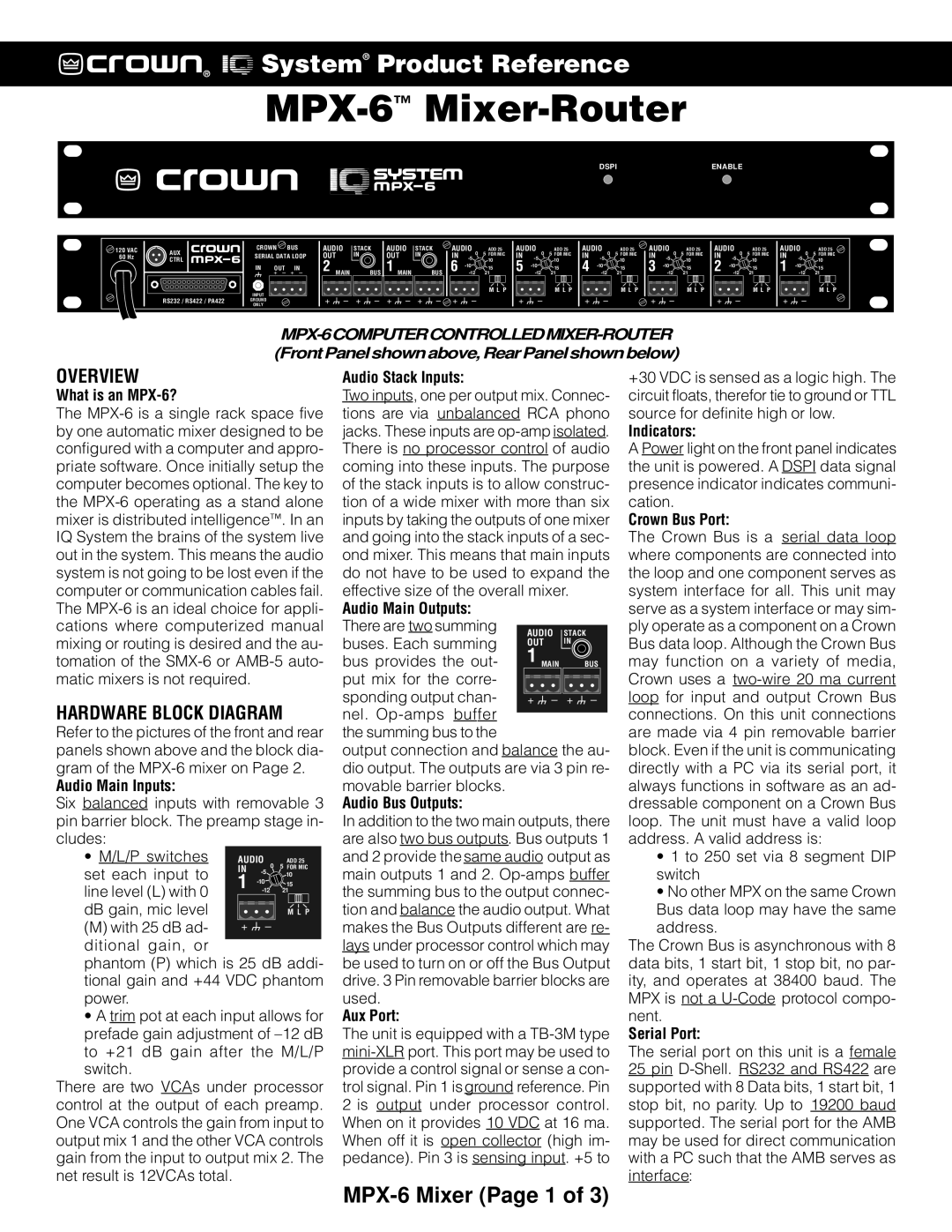
Refer to the pictures of the front and rear panels shown above and the block dia- gram of the
Audio Main Inputs:
Six balanced inputs with removable 3 pin barrier block. The preamp stage in- cludes:
• M/L/P switches | AUDIO | ADD 25 | |||
set each input to | IN | 0 | 5 FOR MIC | ||
10 | |||||
1 |
| ||||
15 | |||||
line level (L) with 0 | |||||
21 | |||||
|
|
|
| ||
dB gain, mic level |
|
|
| M L P | |
(M) with 25 dB ad- | + | – |
| ||
ditional gain, or |
|
|
|
| |
phantom (P) which is 25 dB addi- tional gain and +44 VDC phantom power.
•A trim pot at each input allows for prefade gain adjustment of
There are two VCAs under processor control at the output of each preamp. One VCA controls the gain from input to output mix 1 and the other VCA controls gain from the input to output mix 2. The net result is 12VCAs total.
Audio Stack Inputs:
Two inputs, one per output mix. Connec- tions are via unbalanced RCA phono jacks. These inputs are
effective size of the overall mixer. | ||||
Audio Main Outputs: |
|
|
| |
There are two summing | AUDIO | STACK | ||
buses. Each summing | ||||
OUT | IN | |||
|
| |||
bus provides the out- | 1 MAIN |
| BUS | |
put mix for the corre- |
|
|
| |
|
|
| ||
sponding output chan- | + – |
| + – | |
nel. |
|
|
| |
the summing bus to the |
|
|
| |
output connection and balance the au- dio output. The outputs are via 3 pin re- movable barrier blocks.
Audio Bus Outputs:
In addition to the two main outputs, there are also two bus outputs. Bus outputs 1 and 2 provide the same audio output as main outputs 1 and 2.
Aux Port:
The unit is equipped with a
+30 VDC is sensed as a logic high. The circuit floats, therefor tie to ground or TTL source for definite high or low.
Indicators:
A Power light on the front panel indicates the unit is powered. A DSPI data signal presence indicator indicates communi- cation.
Crown Bus Port:
The Crown Bus is a serial data loop where components are connected into the loop and one component serves as system interface for all. This unit may serve as a system interface or may sim- ply operate as a component on a Crown Bus data loop. Although the Crown Bus may function on a variety of media, Crown uses a
•1 to 250 set via 8 segment DIP switch
•No other MPX on the same Crown Bus data loop may have the same address.
The Crown Bus is asynchronous with 8 data bits, 1 start bit, 1 stop bit, no par- ity, and operates at 38400 baud. The MPX is not a
Serial Port:
The serial port on this unit is a female 25 pin