133472-1A specifications
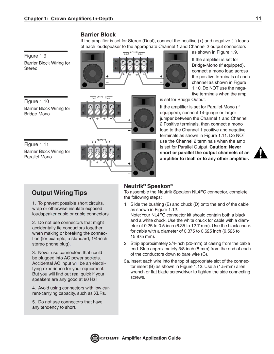
Crown Audio 133472-1A is a sophisticated and highly regarded power amplifier designed for professional audio applications. Known for its reliability and high performance, the 133472-1A is favored by sound engineers, musicians, and event organizers who seek exceptional audio clarity and robust amplification.One of the standout features of the Crown Audio 133472-1A is its impressive power output. This amplifier is capable of delivering substantial wattage, ensuring that it can effortlessly drive a variety of loudspeaker systems without distortion, even at high volumes. This makes it particularly suitable for large venues, concerts, and public gatherings where sound coverage is critical.
The 133472-1A utilizes advanced technologies to enhance its performance. For instance, it incorporates a patented output stage design that minimizes distortion, allowing for a cleaner and more accurate sound reproduction. This is especially important in professional audio environments where audio fidelity is paramount. Additionally, the amplifier features sophisticated thermal management systems that prevent overheating, ensuring reliable operation during extended use.
Another key characteristic of the Crown 133472-1A is its versatility. It is engineered to work seamlessly with a range of audio sources, making it an ideal choice for various applications, including live performances, installations, and broadcasting. Its multiple input options, including XLR and TRS connectors, allow for flexible connectivity options, accommodating various audio setups.
Durability is also a significant aspect of the Crown Audio 133472-1A. Constructed with high-quality materials and robust components, this amplifier is built to withstand the rigors of professional use. Its rugged chassis design provides added protection, making it suitable for both touring and fixed installations.
Furthermore, the Crown 133472-1A offers user-friendly features such as intuitive controls and indicators, allowing users to monitor performance easily. This includes LED status indicators that provide real-time feedback on operation, making it simple to troubleshoot any issues.
In summary, the Crown Audio 133472-1A is a powerhouse amplifier that combines high output, advanced technologies, and durable construction. Its versatility makes it a preferred choice for professionals seeking reliable and superior audio performance in live and installed environments. Whether for music events, speeches, or any high-stakes audio requirements, the 133472-1A delivers the quality and performance essential for exceptional sound.

