4 . 0 | A u d i o C o n n e c t i o n s |
Inputs
For each channel, there is a 1/4” phone jack socket, male & female XLR and pluggable removable terminal block connectors provided for signal input on the rear panel of the amplifier. Each is electronically balanced at an impedance greater than 10k ohms.
The removable terminal block, phone jack and both XLR connectors are internally wired in parallel, and therefore any socket may be used for the input signal. The connectors not used in this manner function as
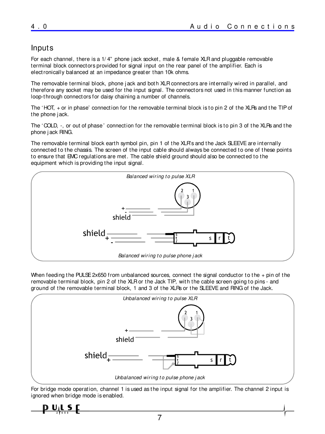
The ‘HOT, + or in phase’ connection for the removable terminal block is to pin 2 of the XLRs and the TIP of the phone jack.
The ‘COLD,
The removable terminal block earth symbol pin, pin 1 of the XLR’s and the Jack SLEEVE are internally connected to the chassis. The screen of the input cable should always be connected to one of these points to ensure that EMC regulations are met. The cable shield ground should also be connected to the equipment which is providing the input signal.
Balanced wiring to pulse XLR
Balanced wiring to pulse phone jack
When feeding the PULSE 2x650 from unbalanced sources, connect the signal conductor to the + pin of the removable terminal block, pin 2 of the XLR or the Jack TIP, with the cable screen going to pins - and ground of the removable terminal block, 1 and 3 of the XLRs or the SLEEVE and RING of the Jack.
Unbalanced wiring to pulse XLR
Unbalanced wiring to pulse phone jack
For bridge mode operation, channel 1 is used as the input signal for the amplifier. The channel 2 input is ignored when bridge mode is enabled.
7
