5 . 0C o n t r o l o p e r a t i o n
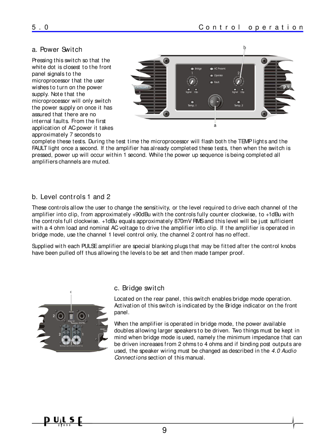
a. Power Switch
Pressing this switch so that the white dot is closest to the front panel signals to the microprocessor that the user wishes to turn on the power supply. Note that the microprocessor will only switch the power supply on once it has assured that there are no internal faults. From the first
application of AC power it takes approximately 7 seconds to
complete these tests. During the test time the microprocessor will flash both the TEMP lights and the FAULT light once a second. If the amplifier has already completed these tests, then when the switch is pressed, power up will occur within 1 second. While the power up sequence is being completed all amplifiers channels are muted.
b. Level controls 1 and 2
These controls allow the user to change the sensitivity, or the level required to drive each channel of the amplifier into clip, from approximately +90dBu with the controls fully counter clockwise, to +1dBu with the controls full clockwise. +1dBu equals approximately 870mV RMS and this level will be just sufficient with a 4 ohm load and nominal AC voltage to drive the amplifier into clip. If the amplifier is operated in bridge mode, use the channel 1 level control only, the channel 2 control has no effect.
Supplied with each PULSE amplifier are special blanking plugs that may be fitted after the control knobs have been pulled off thus allowing the levels to be set and then made tamper proof.
c. Bridge switch
Located on the rear panel, this switch enables bridge mode operation. Activation of this switch is indicated by the Bridge indicator on the front panel.
When the amplifier is operated in bridge mode, the power available doubles allowing larger speakers to be driven. Two things must be kept in mind when bridge mode is used, namely the minimum impedance that can be driven increases from 2 ohms to 4 ohms and if binding post outputs are used, the speaker wiring must be changed as described in the 4.0 Audio Connections section of this manual.
9