CE Series specifications
Crown Audio’s CE Series amplifiers are designed to deliver high performance and reliability for a variety of applications, including live sound, commercial installations, and houses of worship. Renowned for their durability and efficiency, the CE Series combines advanced technology with user-friendly features to appeal to both professional audio engineers and casual users.One of the standout characteristics of the CE Series is its robust construction. Built to withstand the rigors of live events and handling, these amplifiers are housed in a rugged chassis that ensures long-term durability. The fan cooling system is designed for efficient thermal management, keeping the amplifier cool even during extended use, which is crucial for maintaining optimal performance.
The CE Series boasts a range of power options, making it versatile for different setups. With models delivering from 1500W to over 4000W per channel, users can choose the appropriate amplifier to match their specific requirements. This flexibility allows the CE Series to support a wide array of speakers and systems, whether for small venues or large-scale arenas.
Crown utilizes innovative technologies in the CE Series amplifiers. One of the key features is the DSP (Digital Signal Processing), which enhances sound quality and allows for precise control over the audio output. The onboard DSP includes presets for various speaker configurations, EQ settings, and time alignment features, facilitating quick adjustments to achieve the desired sound quality.
Another notable feature is the built-in limiters, which protect both the amplifier and speakers from damage due to overload or clipping. This protection ensures reliability during high-pressure situations, such as concerts or events where audio levels can fluctuate dramatically.
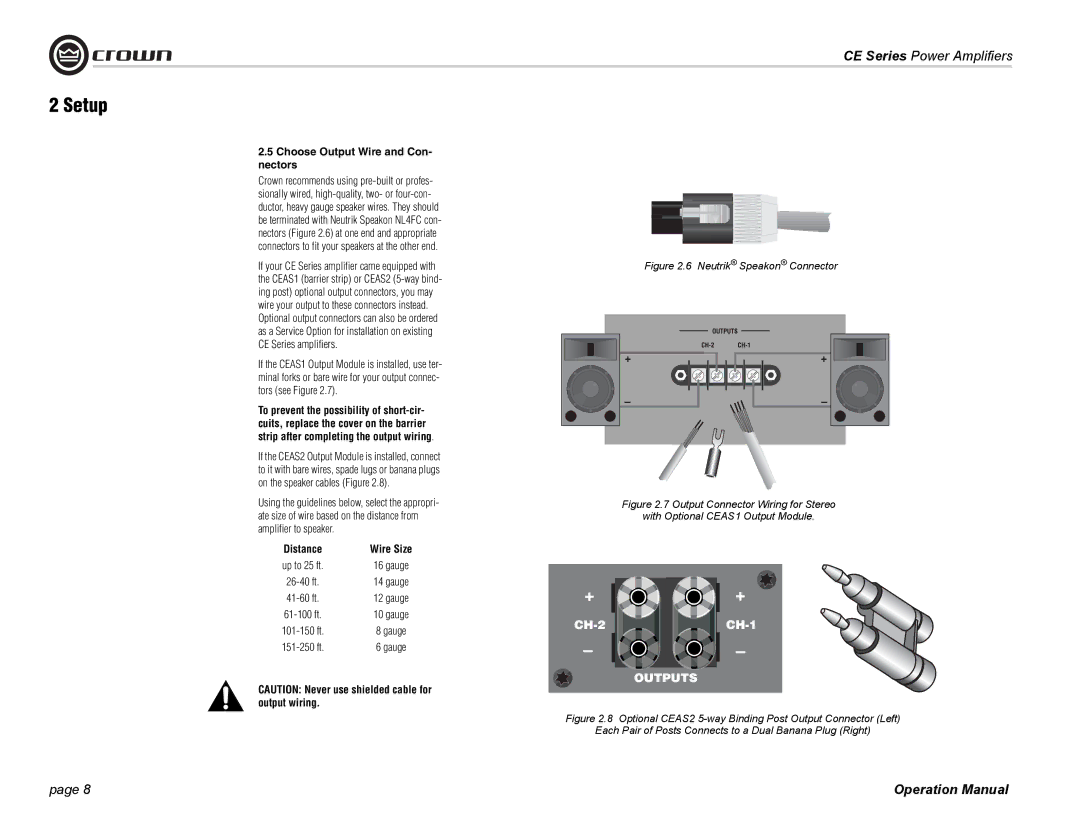
Connectivity options in the CE Series are also comprehensive. The amplifiers come equipped with both analog and digital inputs, allowing compatibility with a wide range of audio sources. Additionally, the rear panel includes speakON® outputs for quick and secure speaker connections.
With its combination of power, reliability, and advanced technology, Crown Audio’s CE Series amplifiers stand out in the crowded field of professional audio equipment. These features make the CE Series an excellent choice for audio professionals seeking quality performance across various applications. Whether for a permanent installation or a touring setup, the CE Series amplifiers deliver the sound, durability, and versatility required by today’s audio engineers.

