4 Operation
4.3Back Panel Controls, Indicators and Connec-
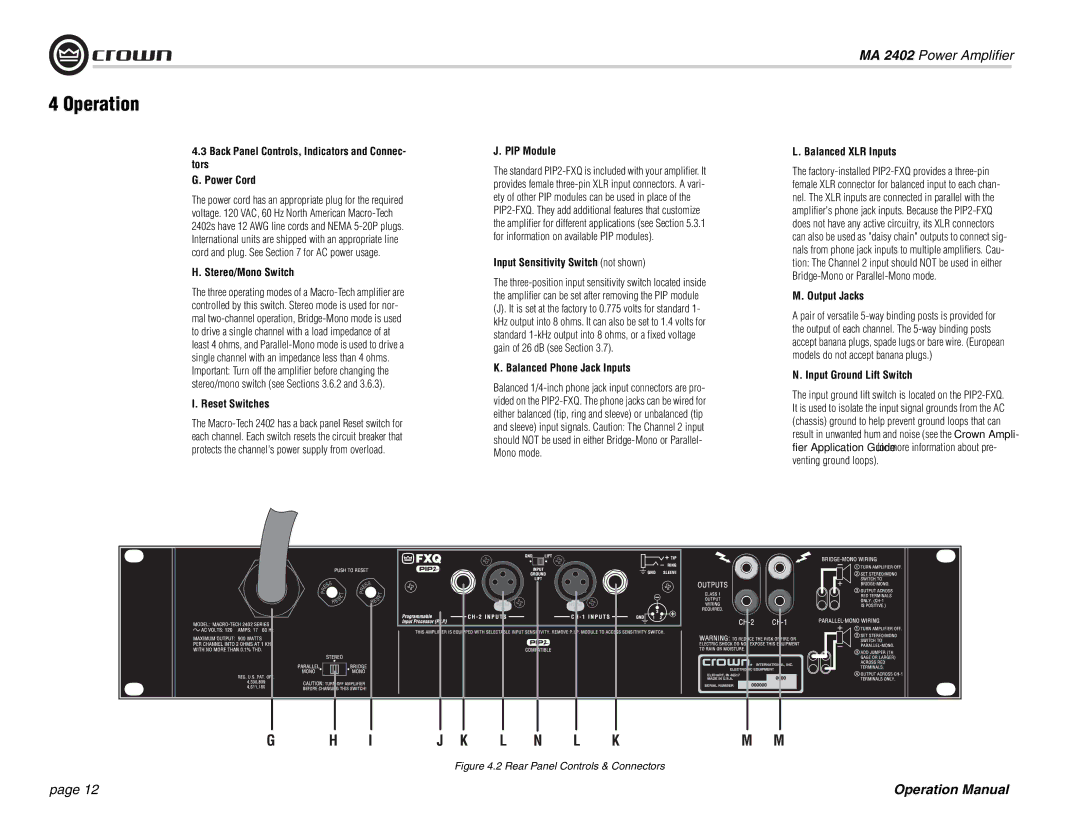
tors
G. Power Cord
The power cord has an appropriate plug for the required voltage. 120 VAC, 60 Hz North American Macro-Tech 2402s have 12 AWG line cords and NEMA 5-20P plugs. International units are shipped with an appropriate line cord and plug. See Section 7 for AC power usage.
H. Stereo/Mono Switch
The three operating modes of a Macro-Tech amplifier are controlled by this switch. Stereo mode is used for nor- mal two-channel operation, Bridge-Mono mode is used to drive a single channel with a load impedance of at least 4 ohms, and Parallel-Mono mode is used to drive a single channel with an impedance less than 4 ohms. Important: Turn off the amplifier before changing the stereo/mono switch (see Sections 3.6.2 and 3.6.3).
I. Reset Switches
The Macro-Tech 2402 has a back panel Reset switch for each channel. Each switch resets the circuit breaker that protects the channel's power supply from overload.
J. PIP Module
The standard PIP2-FXQ is included with your amplifier. It provides female three-pin XLR input connectors. A vari- ety of other PIP modules can be used in place of the PIP2-FXQ. They add additional features that customize the amplifier for different applications (see Section 5.3.1 for information on available PIP modules).
Input Sensitivity Switch (not shown)
The three-position input sensitivity switch located inside the amplifier can be set after removing the PIP module
(J). It is set at the factory to 0.775 volts for standard 1- kHz output into 8 ohms. It can also be set to 1.4 volts for standard 1-kHz output into 8 ohms, or a fixed voltage gain of 26 dB (see Section 3.7).
K. Balanced Phone Jack Inputs
Balanced 1/4-inch phone jack input connectors are pro- vided on the PIP2-FXQ. The phone jacks can be wired for either balanced (tip, ring and sleeve) or unbalanced (tip and sleeve) input signals. Caution: The Channel 2 input should NOT be used in either Bridge-Mono or Parallel- Mono mode.
L. Balanced XLR Inputs
The factory-installed PIP2-FXQ provides a three-pin female XLR connector for balanced input to each chan- nel. The XLR inputs are connected in parallel with the amplifier's phone jack inputs. Because the PIP2-FXQ does not have any active circuitry, its XLR connectors can also be used as "daisy chain" outputs to connect sig- nals from phone jack inputs to multiple amplifiers. Cau- tion: The Channel 2 input should NOT be used in either Bridge-Mono or Parallel-Mono mode.
M. Output Jacks
Apair of versatile 5-way binding posts is provided for the output of each channel. The 5-way binding posts accept banana plugs, spade lugs or bare wire. (European models do not accept banana plugs.)
N. Input Ground Lift Switch
The input ground lift switch is located on the PIP2-FXQ. It is used to isolate the input signal grounds from the AC (chassis) ground to help prevent ground loops that can result in unwanted hum and noise (see the Crown Ampli- fier Application Guide for more information about pre- venting ground loops).