Crown Audio MA-2402 MA 2402 Power Amplifier, Operation Manual, page, 3 Indicators

Models: MA-2402

1 36
Download 36 pages 49.7 Kb
Page 13
Image 13
4.4 Indicators

MA 2402 Power Amplifier

4 Operation

4.4 Indicators

The amber Enable indicator is provided to show that the amplifier has been turned on (or enabled), and that its low-voltage power supply and forced-air cooling system are working. It does not indicate the status of the high-voltage power supplies. For example, the Enable indi- cator will remain lit during unusual conditions that would cause the amplifier's protection sys- tems to put a high-voltage power supply in "standby" mode (see Section 5.1.2).

The amber ODEP indicators confirm the nor- mal operation of Crown's patented Output Device Emulation Protection circuitry. During normal operation, they glow brightly to show the presence of reserve thermal-dynamic energy. They dim proportionally as the energy reserve decreases. In the rare event that there is no reserve, the indicators turn off and ODEP proportionally limits the drive level of the out- put stages so the amplifier can continue safe operation even when conditions are severe. (For a more detailed description of ODEP, see Section 5.1.1.)

The ODEP indicator for the affected channel will turn off if a high-voltage power supply is put in "standby" mode, a high-voltage power supply fuse (or breaker) blows, or a transformer acti- vates its thermal protection circuitry (see Sec- tion 5.1.3). Both ODEP indicators turn off if the amplifier loses AC power, the power switch is turned off or the low-voltage power supply fuse blows.

The green Signal/IOC indicators show sig- nal presence and distortion. As signal presence indicators, they flash with normal intensity in sync with the output audio signals. As IOC (Input/Output Comparator) indicators, they flash brightly if there is any difference between the input and output signal waveforms greater than 0.05%. Because transient distortion hap- pens quickly, a 0.1 second "hold delay" keeps the indicators on long enough to be easily noticed. The IOC function essentially provides proof of distortion-free performance. Note: The Channel 2 IOC indicator will remain lit when running in Parallel-Mono mode.

Under conditions where one of the amplifier's high-voltage power supplies is temporarily put in standby mode, the Signal/IOC indicators will stay on with full brightness. They will resume normal operation when the amplifier is no longer in standby mode.

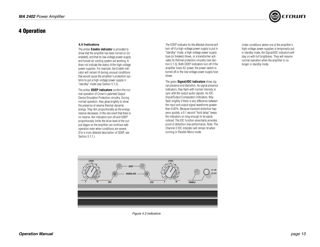
Figure 4.3 Indicators

Operation Manual

page 13

Page 13
Image 13
Crown Audio MA-2402 operation manual MA 2402 Power Amplifier, Operation Manual, page, 3 Indicators